Dynamic Light Tracking System Prototype
Posted: December 12, 2020 Filed under: Uncategorized Leave a comment »By: Kenneth Olson
(Iteration 3)
Approach
For this project I wanted to build off what I learned from the previous iteration. In Iteration 2 I utilized the “Eyes ++ Actor” to manipulate objects on a computer screen by using my fingers, a web camera, black tape, and a table top to create an interactive Sci-fi user interface. This time around I wanted to create an even easier, more approachable, way to make objects on a screen move in correlation to how the user moves. A more intractable and abstract system than previous. The system utilizes the “Eyes ++ Actor” and the contrasting qualities of physical light and the void of darkness, with a web camera. The overall system is simple, however, depending on the case usage could result in complicated outputs.
The system works as follows. First, in the middle of a dark room, the user will use their phone flashlight to wave around (the user could be responding to music through dance, or other forms of stimulus that would cause the human body to move freely). Second, A web camera, facing the user, will then feed into Isadora. Third, the web camera output would then connect to the “Eyes ++ Actor” to then affect other objects.
With this system I discovered an additional output value I could utilize. Within Iteration 2 I was limited to only “X” and “Y” values of the “Blob Decoder” coming from the “Eyes ++ Actor” .In iteration 3 I also had “X” and “Y” values to play with (because the light from the flashlight was high enough contrast from the black darkness for the “Eyes ++ Actor” to track) My third output, as a result of using light, was the brightness output of the “Eyes ++ Actor”. Unlike before, in Iteration 2, the size of the object in the tracking area did not change significantly, if at all. However, in Iteration 3 the amount of light shown at the Web Camera would drastically change the size of the object being tracked, resulting in more or less of the tracking area to be filled with white or black. So by using one dynamic contrasting light value as an input to the “Eyes ++ Actor” I was able to affect several different objects in several different ways. This discovery only came about from playing around with the Issadora system.
With this dynamic light tracking system, I made ten different vignettes with different interactable objects and videos. Bellow are just a few examples:
Vignette 1
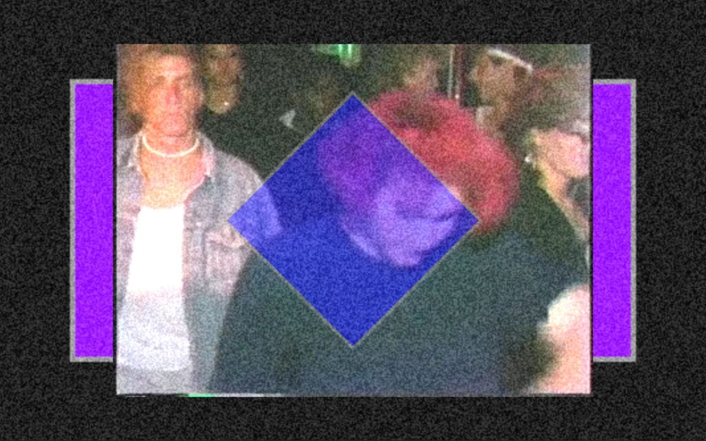
In this scene the blue and purple shapes would change scale with the addition of more or less light.
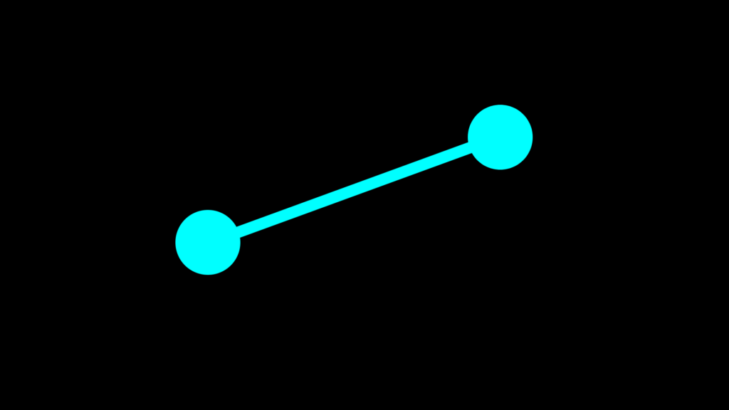
Vignette 2
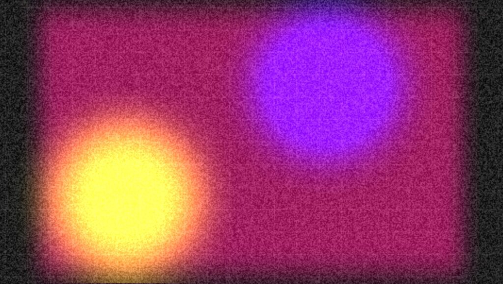
In this scene the two colored circles would move in both “X” and “Y” directions in correlation to the light’s position within the tracking area. And a white grid would appear and overlay the circles with the addition of more light and the grid would fade away with less light.
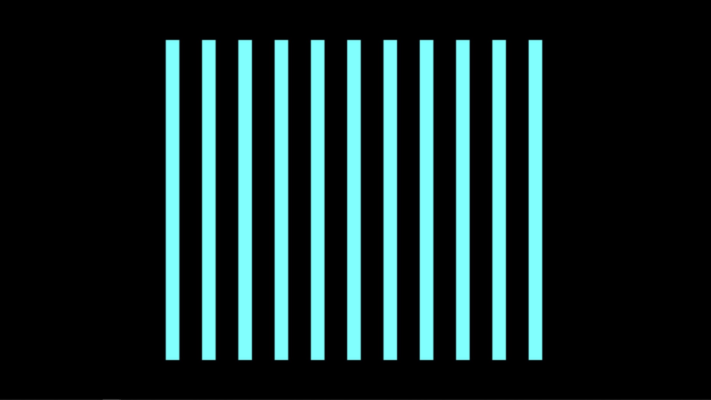
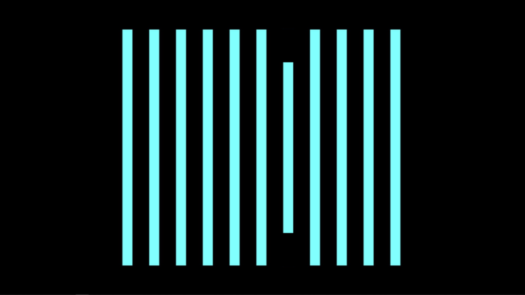
Vignette 3
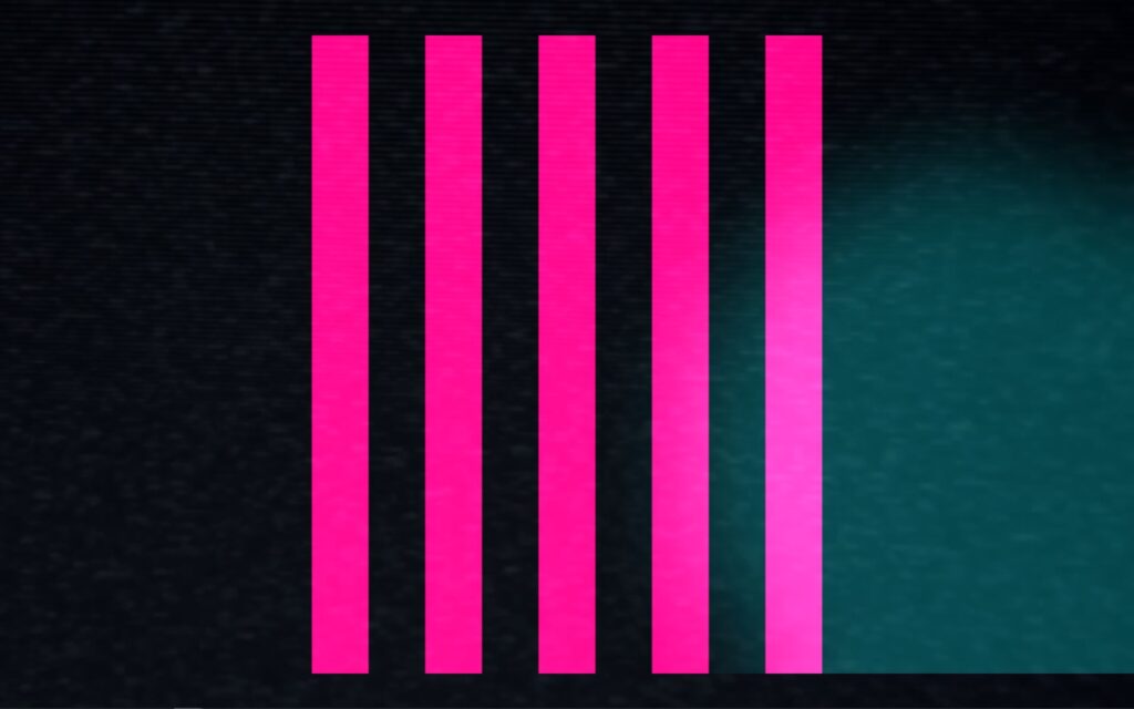
In this scene the pink lines would squash in succession when the light source moves from left to right or from right to left. (this scene was inspired by my iteration 2 project)
Assessment
Overall I found this system to be less accurate or less controllable for precise movements, when compared to iteration 2. I could imagine with a more focused amount of light the system would behave better. However, the brightness value output was very responsive and very controllable. I did not try using multiple light sources as an input, but with too much light the system does not function as well. I would love to see this system integrated into a large in person concert or rave with every member of the audience wearing a light up bracelet, or something. But as a party of one, I used a projector as an output device for this system and created a mini rave for one, in my apartment. I used my phone light and also played music from my phone. With even more projectors in the space I could imagine the user would become even more engaged with the system.
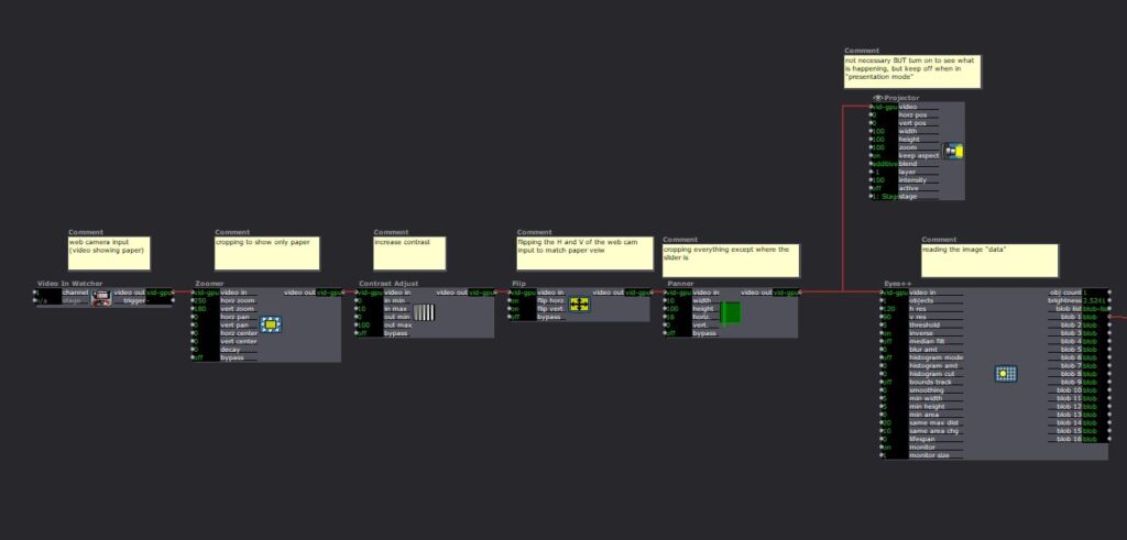
Isadora Patch:
Intractable Motion Tracking User Interface Prototype
Posted: December 12, 2020 Filed under: Uncategorized Leave a comment »By Kenneth Olson
(Iteration Two)
Inspiration
I was inspired by science fiction user interfaces (UI) from movies like: “Oblivion” and “Minority Report” and other UI work from the motion designer, Gmunk. I wanted to try and create a real high tech interactable UI system using approachable low tech. This is so others could easily recreate this system. The above Image is the sample inspiration I made inside of Isadora. In the patch, the dots flash on and off, the numbers change, the lines move back and forth, and the circles rotate. Everything in the patch (except for the black grid) was made inIsadora and moved using several “Wave Generator Actors” and “Shape Actors.”
Approach
In most of the movies examples of “future UI” The actors are interacting with some sort of black or clear display, and are using their hands as an input to alter or affect the objects on the display. To get Isadora to listen/follow my hands I used the “Eyes ++ Actor,” a web camera, black tape, and a white table top. My goal was to keep the overall system approachable and simple to create, and a web camera with black tape seemed to be the simplest tools for the job.
The system works by: first, wrapping the users index fingers with black tape. Second, set up the web camera in a top down orientation, looking down at the users hands. Third, use a white table top, or a white sheet of paper works great, (this creates a high contracting image for isadora to track). Finally, direct the web camera output into an “Eyes ++ Actor”. From here anything is possible. Depending on lighting and other conditions, I found it helpful to add some extra Isadora Actors to make the system run smoother. (as shown below).
Eyes ++ Actor
The “Eyes ++ Actor” works great for this system, however, results may vary for other people. I was able to track up to three fingers at a time with relative ease. I should also note the “Eyes ++ Actor” works by following the brightest object in the scene, So by using a white table and black taped fingers I needed to turn “inverse” ON in the “Eyes ++ Actor” settings. I also assume this system will also function with a black table/background with white taped fingers. In this scenario you would keep the “inverse” setting to OFF in the “Eyes ++ Actor” settings. Because my hands are so white they blended into the white table easter, but for people with significant darker skin than mine, I would suggest using white tape with a darker table.
Uses and Examples
I used this system three different ways:
1) piano
2) connect the dots
3) multiple sliders.
Piano
In this system, when I moved my finger, with the tap on it, from left to right or right to left the lines on the screen would shrink. Sound could be added within this system, like a piano note when each line is triggered.
Connect The Dots
In this system, I used both hands. I have tape on my left and right index finger. The left dot is following my left index finger and the right dot is following my right index finger. The line is being auto generated with the “Lines Actor” and will always follow and connect the two dots together.
Sliders
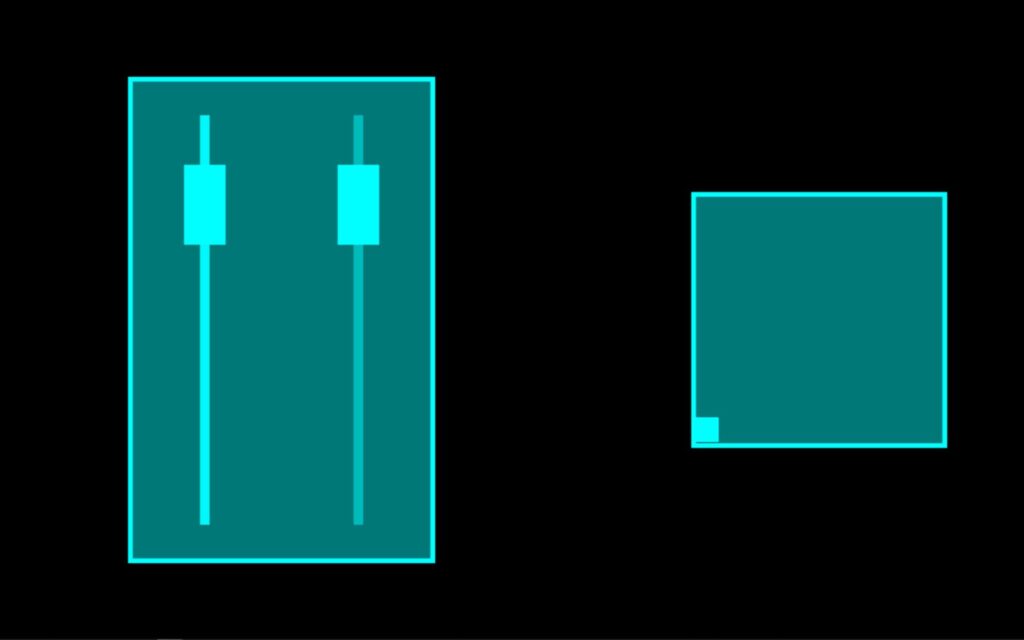
In this system I have two different sliders. The slider on the left controls the horizontal position of the small square found in the box on the right. And the Slider on the right controls the vertical position of the small square. When used together the square can move around within the box. An important feature I wanted to create with these sliders was when one slider was in use the other sider would not move. I accomplished this with the use of the “Panner Actor” to select a specific area of the web camera output to watch. As with the other systems the “Eye’s ++ Actor” was using the entire web camera output to read and follow my taped finger. However, by using the “Panner Actor” I could scale down what the “Eye’s ++ Actor” could see, this focused the web camera output to a specific range. Meaning the “Eye’s ++ Actor” could only see my finger within a specific area of the table.
Assessment
With the time I had I accomplished what I set out to do by creating a hand controlled science fiction user interface. I would have liked to been able to put all of the systems I created for this project together, however, my computer wouldn’t allow such things to happen. For future iterations I would like to play with scale more. Perhaps replace the finger with a human body and have the “Eye’s ++ Actor” follow the human form. The “Eye’s ++ Actor” did work most of the time, but I did lose the tracking of my finger sometimes causing the visuals in the “Projector Actor” to “glitch out” not sure what was causing this issue weather it was the web camera, the “Eye’s ++ Actor”, or maybe the several other actors I used to edit the webcam footage. I would also like to find a way for the user to be touching the objects being affected in Isadora. Meaning, the user could touch the computer screen or a projection screen and the objects being projected would look like they were directly following the users hands on the screen, instead of the objects indirectly following the movement of the hands on the white or black table.
Isadora Patch:
Depth Camera CT Scan Projection System
Posted: December 5, 2020 Filed under: Uncategorized Leave a comment »by Kenneth Olson
(Iteration one)
What makes dynamic projection mapping dynamic?
Recently I have been looking into dynamic projection mapping and questioned what makes dynamic projection mapping “Dynamic”? I asked Google and she said: Dynamic means characterized by constant change, activity, or progress. I assumed that means for a projection mapping system to be called “dynamic” something in the system would have to involve actual physical movement of some kind. Like the audience, the physical projector, or the object being projected onto. So, what makes dynamic projection mapping “dynamic” well from my classification the use of physical movement within a projection mapped system is the separation between projection mapping and dynamic projection mapping.
How does dynamic projection mapping work?
So, most dynamic projection systems use a high speed projector (meaning a projector that can project images at a high frame rate, this is to reduce output lag). Then an array of focal lenses and drivers are used (to change the focus of the projector output in real time). A depth camera (to measure the distance between the object being projected onto and the projector) and then a computer system with some sort of software to allow the projector, depth camera, and focusing lens to talk to each other. After understanding the inner workings of how some dynamic projection systems work I started to look further into how a depth camera works and how important depth is within a dynamic projection system.
What is a depth camera and how does depth work?
As I have mentioned before, depth cameras measure distance, specifically the distance between the camera and every pixel captured within the lens. The distance of each pixel is then transcribed into a visual representation like color or value. Over the years depth images have taken many appearances based on different companies and camera systems. Some depth images use gray scale and use brighter values to show objects closer to the camera and darker values to signify objects further in the distance. Each shade of gray would also be tied to a specific value allowing the user to understand visually how far something is from the depth camera. Other systems use color, while using warmer versus cooler colors to measure depth visually.
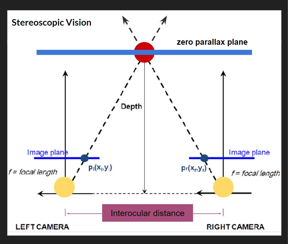
How is the distance typically measured on an average depth camera?
Basically most depth cameras work, the same way your eyes create depth through “Stereoscopic Vision”. For this Stereoscopic Vision to work you need two cameras (or two eyes) in this top down diagram (pictured above), the cameras are the two large yellow circles and the space between them is called the interocular (IN-ter-ocular) distance. This distance never changes, however, this ratio needs to be at a precise distance because if the interocular distance is too close or too far apart the effect won’t work. On the diagram the dotted line shows the cameras are both looking at the red circle. The point at which both camera sight lines cross is called the zero parallax plane, and on this plane all objects are in focus. This means every object that lives in front and behind the zero parallax plane is out of focus. Everyone at home can try this, If you hold your index finger a foot away from your face, and look at your finger, everything in your view, except your finger, becomes out of focus, and with your other hand slid it left and right across your imaginary zero parallax plane, with your eyes still focused on your finger you should notice your other hand is also in focus. There are also different kinds of stereotypes, another common type is Parallel, on the diagram, the two parallel solid lines coming from the yellow circles point straight out. Parallel means these lines will never meet and also mean everything will stay in focus. If you look out your window into the horizon, you will see everything is in focus, the trees, buildings, cars, people, the sky. For those of us who don’t have windows, Stereoscopic and parallel vision can also be recreated and simulated inside of different 3D animation software like Maya or blender. For those who understand 3D animation cameras and rendering, if you render an animation with parallel vision and place the rendered video into Nuke (a very expensive and amazing node and wires based effects and video editing software) you can add the zero parallax plane in post. This is also the system Pixar uses in all of its animated feature films.
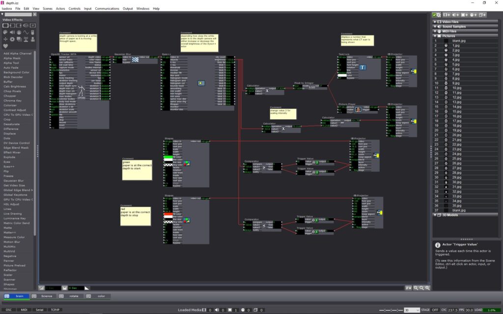
Prototyping
After understanding a little more about how depth cameras work I decided to try and conceive a project using an Astra Orbbec (depth camera), a pico projector (small handheld projector), and Isadora (projection mapping software). Using a depth camera I wanted to try and prototype a dynamic projection mapping system, where the object being projected onto would move in space causing the projection to change or evolve in some way. I ended up using a set of top down human brain computed tomography scans (CT scans) as the evolving or “changing” aspect of my system. The CT scans would be projected onto regular printer paper held in front of the projector and depth camera. The depth camera would read the depth at which the paper is at in space. As the piece of paper moves closer or further away from the depth camera, the CT scan images would cycle through. (above is what the system looked like inside of Isadora and below is a video showing the CT scans evolving in space in real time as the paper movies back and forth from the depth camera) Within the system I add color signifiers to tell the user at what depth to hold the paper at and when to stop moving the paper. I used the color “green” to tell the user to start “here” and the color “red” to tell the user to “stop”. I also added numbers to each ST scan image so the user can identify or reference a specific image.
Conclusion
The finished prototype works fairly well and I am very pleased with the fidelity of the Orbbec depth reading. For my system, I could only work within a specific range in front of my projector, this is because the projected image would become out of focus if I moved the paper too far or too close relative to the projector. While I worked with the projector I found the human body could also be used inplace of the piece of paper, with the projected image of the SC scans filling my shirt front. The projector could also be projected at a different wall with a human interacting with the depth camera alone, causing the ST scans to change as well. With a more refined system I can imagine this could be used in many circumstances. This system could be used within an interactive medical museum exhibit, or even in a more professional medical setting to explain how ST scans work to child cancer patients. For possible future iterations I would like to see if I could incorporate the projection to better follow the paper, having the projector tilt and scale with the paper would allow the system to become more dynamic and possibly more user friendly.
(PP3) Mystery Box Game Instructions and Reflection
Posted: October 15, 2020 Filed under: Uncategorized Leave a comment »By Kenny Olson
objective:
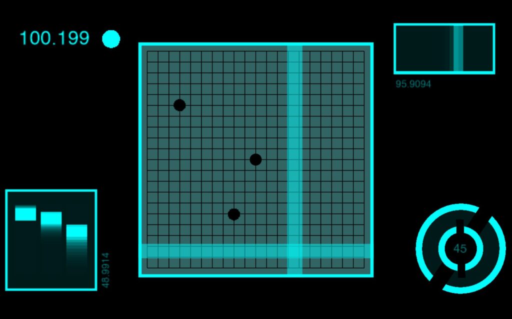
You are the white cube (bottom left corner). Shift and dodge away from the color changing bad guy (top right corner), who is protecting the color changing rainbow gold. You have three lives to collect as much rainbow gold as possible. As you steal more and more rainbow gold the bad guy will get more and more upset. The bad guy will do whatever it takes to protect and hide the rainbow gold. How much gold can you steal, and how long can you last!?!?!
Instructions:
- Plug the “Mystery Box” (Makey Makey) into the computer. Plug the Leap Motion into the computer. At this time do not touch the box until the “game starts” (If you don’t have the “leap motion” or the “Mystery Box”, the game can still be played, and you may skip this first step.)
- Download and open the Mystery Box zip file and open the Isadora File found within. Then immediately open the Isadora preview window full screen. hot key: (command + sift + S)
- A pink and blue loading bar will appear, the game is loading, wait till loading bar fills and the main title will appear.
- The main title will play music (adjust volume accordingly). Text will then flash saying “swipe hand to start” (swipe hand over the leap motion) to start playing. (If you don’t have the leap motion you may press the space bar or the zero key on the keyboard.)
- The main title and music will fade away and the game will start.
- To play the game. Pick up the “Mystery Box” and try touching random sides of the box together with your hands to move the white cube (found in the bottom corner at the start of the game). (The keyboard may also be used to move the white box around by using the arrow keys.) The smaller blinking box is the “rainbow gold” (meant to be collected). The colored box moving towards the white box (found in the top right corner at the start of the game) is the “bad guy” (say away form it).
- When you loose all three of your lives the game will end and present your final score. You will then be redirected to the main title screen. (jump back to step four.)
NOTE:
To achieve the best playing experience adjust your Isadora screen preview window ratio to 1920 by 1080.
Game Download:
Reflection:
I started this project in hopes to make a NES (Nintendo Entertainment System) look alike game, with an 80s/90s retro vibe. I referenced a lot of game systems to understand what kids of game I wanted to make. Gauntlet was one game that stood out the most. Gauntlet is a top down, roguelike, dungeon crawl type game. The game itself is never ending, however, gets progressively harder the farther the players get into the game. In the game players collect gold, potions, and food while trying to find the exit to the next level. While doing so there are different types of non playable “bad guys” who try to kill or harm the “good guys”.
In my game I wanted to try and recreate as much of the Gauntlet game system as I could. After talking with Alex I quickly understood how to allow players to control a characters movement around the screen. Alex said to think of the playing area like a grid and the character is jumping/moving from grid box to grid box. to get the character to move I used keyboard watcher actor (tied to the arrow keys) triggering a counter actor. The counter actor incrementally increased and decreased the horizontal and vertical values of the character (which in my game was a colored square made from a shapes actor) so when the arrow keys were pressed the character could move. For the bad guy I used the same system as for the good guy, however, the bad guy needs to both move on its own and chase/follow the good guy. I did this with a comparator actor, I took the horizontal and vertical values of the good guy and the horizontal and vertical values of the bad guy and fed both the horizontal values into one comparator actor and both vertical values into their own comparator actor. I then set each comparator actor to trigger the bad guy to move if the bad guys horizontal and vertical values are not equal to the good guys values. Not included in the Gauntlet game was a life counter/display. In the game I made, I gave the player three lives/chances to be killed before the game would reset from the start. Inside Isadora the code looks more complicated than what is happening. Basically, what is happening is if the horizontal and vertical values from the good and bad guy are the same, one of the three shapes actors (displayed in the top left of the active game window at the start of each game signifying three lives) is turned off. After this event happens a third time, a jump actor is triggered and sends the player to a “GAME OVER SCREEN” with the players score displayed, then sending the player back to the title screen. The game then resets. In Gauntlet, players collect items in the game (like gold and food) and exit each level by standing over an exit door. In my game, A character is tasked with collecting a small flashing cube (I called rainbow gold, because it changes colors) the when the character lands on a rainbow gold square several things happen. First, the players score increases by “100”. Two, the stage, obstacles, the bad guy, and the rainbow gold all changes colors (signifying a change in level). Third, the rainbow gold “randomly” changes its position to a new spot in the playing. As the player accumulates points by collecting “rainbow gold” the score increases and when the score increases several things happen. First, for every 1,000 points added to the score the bad guy moves faster (up until 10,000 points). Second, As the score gets higher several different sized squares appear over the playing area, and block the players view. The game still functions as usual, however, when the rainbow gold appears behind the “view blocking” square area, the player needs to then search with these areas to find the gold. When the bad guy or good guy enter these areas they also become obscured from view. This adds a much needed tension and strategie to the game play.
The most challenging aspect of this game to create was the character movement system (as explained prior). The system I created worked great (after exploring and testing several different systems before), however, the system I ended with could not function with negative numbers. This meant I had to manually shift the origin of the projector actor from the center of the preview screen, to the bottom left corner of the preview screen. (As shown below) the origin is the (0,0) usually found in the center of a projector actor preview window in Isadora. To insure all the characters would always land on a set of positive coordinates I had to physically zoom into the top right area of the screen . By doing this I ran into some scaling problems and gained some granularity with the objects that needed to interact with the grid (so the good guy and bad guy square shapes actors, the rainbow gold square shapes actor, the grid image I used in the background, and the view obscuring squares also made from the shapes actor). I overcame the fuzzy and granular look by adding more noise grain to the overall composition to help unify and make everything feel purposeful.

In the end the overall game works great, but there are some small glitches that happen from time to time. One glitch is the game will start the player off with two lives instead of three, even though the three squares (representing the player having three lives) in the top left of the screen are visible, under the hood, the code shows the player has already lost a life. Another glitch is sometimes the bad guy could take a life away from the good guy by only being on one of the same horizontal or vertical access as the good guy, this would also cause the bad guy to move around the screen in an odd way. Most of the glitches happen after the game ends (for whatever reason) the game does not fully reset when a new game starts.
If I were to continue with this game I would like to add more bad guys over time, a way for the player to gain an extra life, possibly grow and shrink the playing grid area, A scoreboard with player names. I also think adding a character selection screen would be interesting, the player could choose between different shapes to play as, and each shape has different abilities.
Using Isadora as a video game development software for RPGs is probably not something the developers meant for Isadora to be used as, and it shows. Regardless this was A fun experiment.
Pressure Project 2 – Kenny Olson
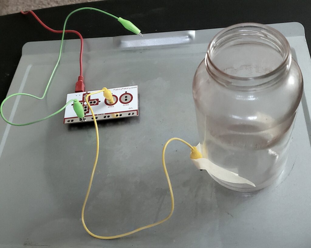
Posted: October 3, 2020 Filed under: Uncategorized Leave a comment »For project 2, I made a Randomized Nicki Minaj Meme Generator Hydration Station System. The system set up is: a water glass reseting on a metal tray, and when the glass is picked up off the try, a random Nicki Minaj Meme audio clip is played. The mechanics of the system involve a Makey Makey. With one set of alligator clips connected to the metal try and the earth (or grounding) connection on the Makey Makey (the green wire shown below). With another alligator clip, one end is connected to the space button on the Makey Makey with the other alligator clip end taped to a water glass (the yellow wire shown below) with a metal conduction string in the alligator clips mouth. The sting goes under the glass and is secured on the adjacent side with more tape. When the water glass is placed on the metal tray, the string on the bottom of the glass makes contact with the tray, sending a signal to the Makey Makey telling it to trigger the space bar.
Inside of Isadora, a “keyboard watcher actor” (with direction set to: UP) triggers an “envelop generator++ actor” with a one second rate with a starting rate of 0 and an ending rate of 100. When the “envelop generator++ actor” ends, the end trigger goes in two directions. Direction one triggers and displays a number, counting the times the system is triggered. The second direction triggers a random audio sound from a preselected list of ten sound. Direction one works by, the “ADD” on a “counter actor” with a min value of 1 and max value of 101, and mode set to wrap. The output number is then fed into the line “Text/ure actor”. The text document connected to the “Text/ure actor” (accessible when the actor is double clicked) has a list of numbers from 0-100 displayed vertically. Finally the video out of the “Text/ure actor” is fed into a “projector actor”. Direction two works by, the “envelop generator++ actor” triggering a “random actor” the “random actor” produces a random rational number between the values of 1 and 100. The value from the “random actor” is then fed into a “float to integer actor” to get a natural number. This number is then sent to ten deferent “inside range actors”. each “inside range actors” is set to only trigger if the number given is between the predetermined values. Each of the ten “inside range actors” are set incumbently to only accept 10 numbers. So the first “inside range actors” only accepts numbers “1, 2, 3, 4, 5, 6, 7, 8, 9, and 10” and the next “inside range actors” only accepts numbers ” 11, 12, 13, 14, 15, 16, 17, 18, 19, and 20″ so on and so forth until 100. Next each of the “inside range actors” is fed to its own “envelop generator++” from the “inside range actors” enter to the “envelop generator++” trigger. The “envelop generator++” output is then connected to the play length of a “movie player actor”. The result is, when the “random number actor” is triggered, and formatted correctly, each “inside range actors” will read said number and determine whether or not trigger the “envelop generator++” to then play the audio.
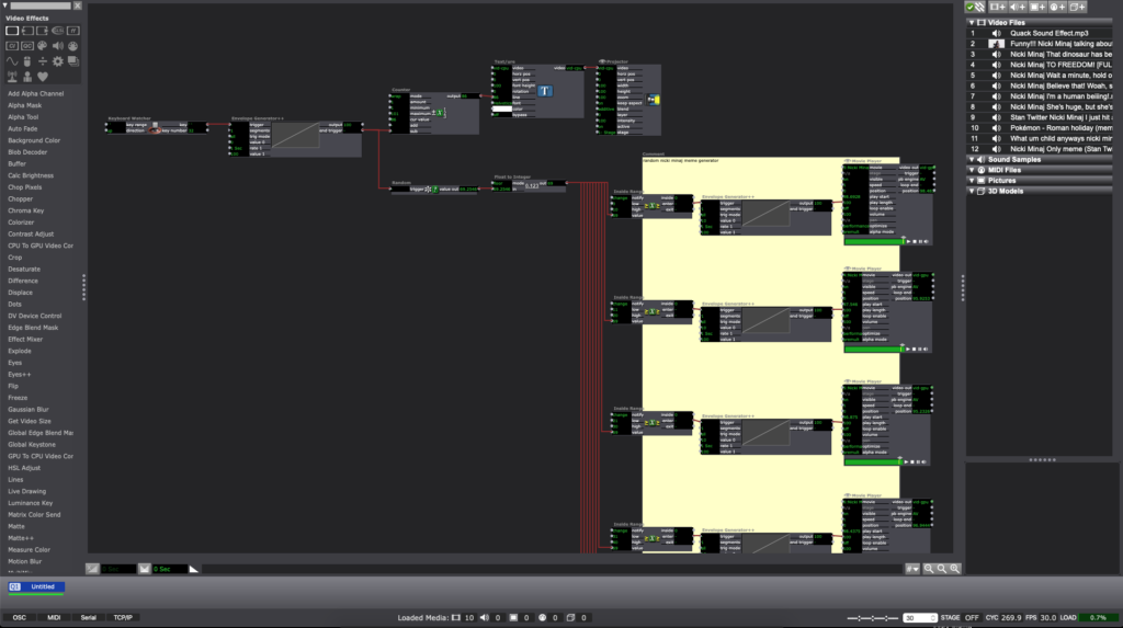
In the end, the system will run something like this: a person picks up the water glass from the tray, with a one second delay, a random audio sound will play (in my case a Nicki Minaj meme), and a number will be displayed, counting the number of times the glass is lifted or “drank from”.
Reflections:
Originally I wanted a sound to play after I opened my desk drawer and also count the times said door was opened, however, I found trying to make a button with the Makey Makey difficult with the limited arts and crafts tools I have. Inside of Isadora, Changing the direction of the “keyboard watcher” from down to up was a crucial and important revelation. Also, finding a way to visualize the automated counting system was the hardest part of this project. Once I found the “Text/ure actor” everything became much smoother.
Crutique:
During the critique, an interesting discussion about culture came about. “what if instead of a meme sound played, a video of someone needing water was projected, when someone picked up the water glass?” in the right setting or context a simple gesture with relatively simple tech could have astronomical cassations and implications.
Pressure Project 1
Posted: September 10, 2020 Filed under: Uncategorized Leave a comment »Kenny Olson
This video was what I used as inspiration for this project: https://www.youtube.com/watch?v=yVkdfJ9PkRQ
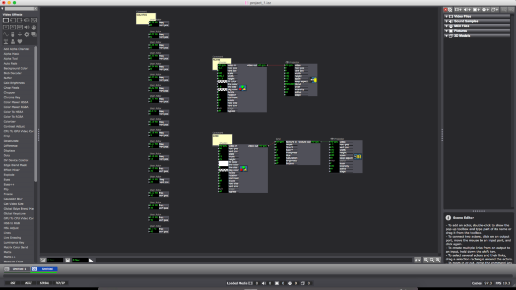
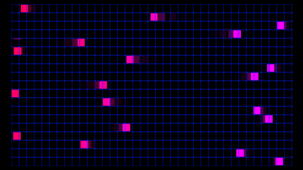
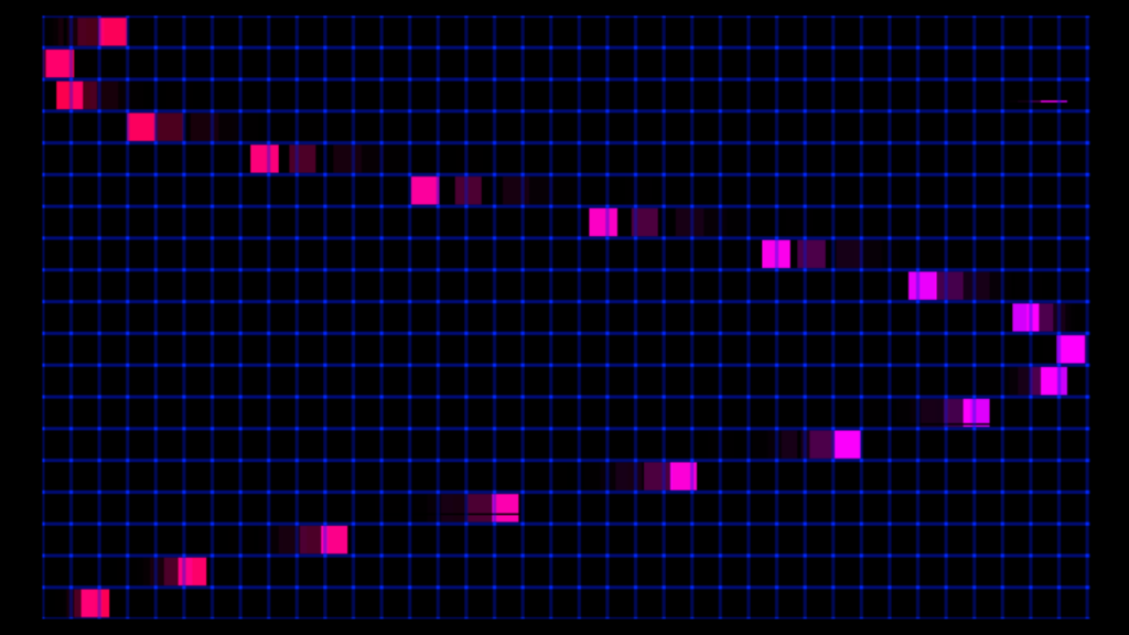
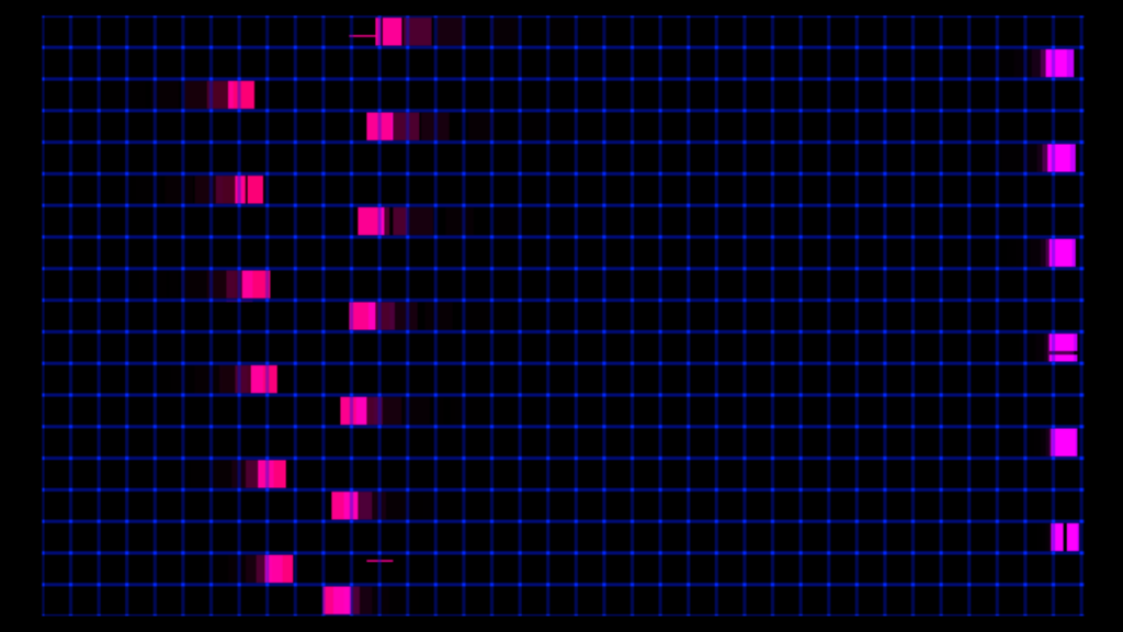
I wanted to create a looping and evolving “vaporwave aesthetic” visualization in Isadora. I found a video (linked above) of different length pendulums swinging and I wanted to try and recreate it. Once the Math was figured out the overall pattern was very simple. I added A black frame and a grid for aesthetic purposes (the ‘Nodes’ pictured above). The main chunk of the magic lives inside of the ‘User Actors’.
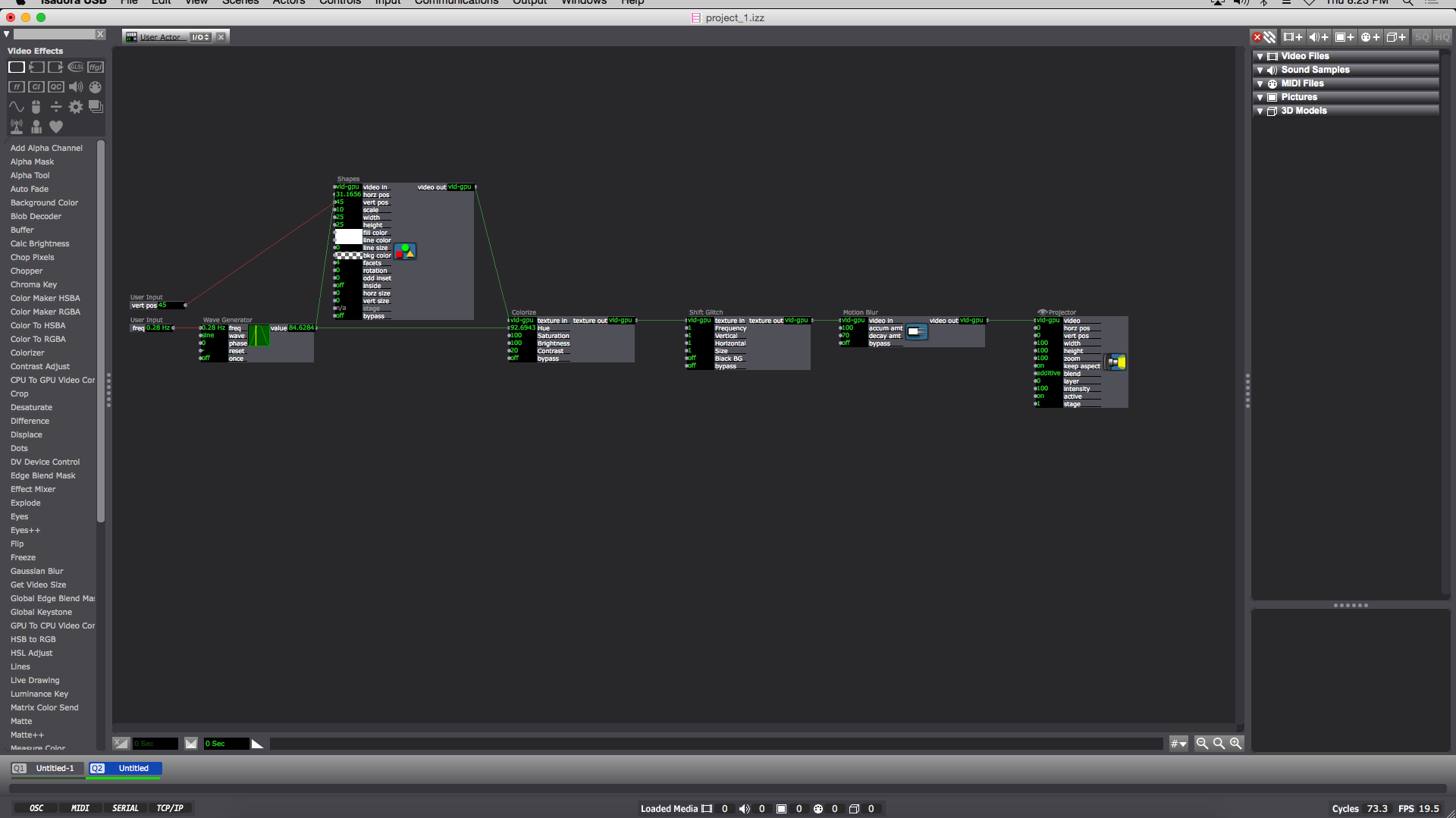
Inside each ‘User Actor’ Is a ‘Wave Generator’ feeding into the ‘Hue’ of a ‘Colorize Node’ (the min and max of the ‘Colorize Hue’ are min:80 max:95) and the ‘horizontal position’ of the ‘Shapes Node’. The ‘Shape Node’ ‘scale value’ is 10. Then the ‘Shapes Node’ ‘video out’ feeds into the ‘Colorize Node’ ‘texture in’. Next the ‘Colorize Node’ goes into the ‘texture in’ of a ‘shift Glitch Node’ (this is for looks and adds a fun glitching effect). I should also note the values of: ‘frequency’, ‘vertical’, ‘horizontal’, and ‘size’ on the ‘Shift Glitch Node’ are all set at 1. Then the ‘texture out’ of the ‘Shift Glitch’ goes into the ‘video in’ of a ‘Motion Blur Node’ with ‘accumulation amount’ set to 100 and ‘decay amount’ set to 70. Next the ‘video out’ of the Motion Blur Node’ goes into the ‘video’ of a ‘Projector Node’. Finally I added a ‘User Input Node’ into the ‘vertical position’ of the ‘Shapes Node’ and another ‘User Input’ into the ‘frequency’ of the ‘Wave Generator Node’. When completed the result should look like something similar to the above image. (you can now ‘save and update all’ and leave the ‘User Actor Window’ )
Now this is when the Fun starts. Back in the main composition window of Isadora you should have a newly created ‘User Actor’ with 2 adjustable values (‘frequency’ and ‘vertical position’). To get started adjust the ‘frequency’ to 0.28 Hz and the ‘vertical position’ to 45. You can then duplicate the ‘User Actor’ as many times as you please. The trick is to subtract 0.01Hz from the ‘frequency’ and subtract 5 from the ‘vertical position’ in a descending pattern with every additional ‘User Actor’ (My 1st ‘User Actor’ starts with a ‘frequency’ of 0.28 Hz and a ‘vertical position’ of 45 ending with my 19th ‘User Actor’ with a ‘frequency’ of 0.1 Hz and a ‘vertical position’ of -45)
To reset the program simply reenter the current scene from a previous scene (with a “Keyboard Watcher Node” and a “Jump++ Node” or by using the ‘space bar’)
I should also note: as long as all the ‘User Actors’ are separated by a constant ‘frequency’ and ‘vertical position’ (or ‘horizontal position’) value from each other (in either a positive or negative direction) the pattern will continue on forever in said direction.
A fun thing about creating this mathematical visualization digitally is there is no friction involved (as shown in the video example, eventually the balls will stop swinging) meaning this pattern will repeat and never stop until Isadora is closed.
Project Bump
Posted: September 8, 2020 Filed under: Uncategorized Leave a comment »https://dems.asc.ohio-state.edu/wp-admin/post.php?post=1761&action=edit
The pictures of this project immediately got my attention. With a group of people standing in a space together with, what looks like, a projection on the floor and a wall with several dots. I love the idea of creating an experience that was playful, interactive, tricky, and physically engaging. Modernizing a board game like Candy Land with projections and body movement. so cool!