Cycle 3 – Stanford
Posted: December 14, 2020 Filed under: Uncategorized Leave a comment »For Cycle 3 I had to rethink the platform I was using to transport my Sketchup model from my computer to VR. I was having issues with all of the shapes loading in SentioVR and the base subscription didn’t allow me to use VR at all. This made me look into an extension called VR Sketch.
This ended up being a way better program. You are able to make edits while in VR and even have multiple people in the model at the same time. The render quality is not as great though.
I think my favorite thing about the program was the workflow. I used it a few times over the past couple weeks while working on other class projects. I was able to make quick sketches models for a design I was working on and put myself in it in VR to see if it worked the way I thought it was working. Then I could make changes and go back in VR within minutes. It made the way I design a lot different. I now have a practical way to see the way an audience is going to experience something before it is built and make changes accordingly.
Cycle 3 – Final Project
Posted: December 13, 2020 Filed under: Uncategorized Leave a comment »In this iteration of the project, I completed a more robust prototype of the box, which allows a more usable interface while calling cues.


The box evolved between cycle two and three, but adding all of the wires and the grounding option. In cycle two, the box mainly just had the spot outlined for the Makey Makey, and the top of the box had numbers painted on. I improved by then adding all of the wires, cutting the holes for the box, and securing everything inside the box.
The patch did not change from cycle 2.
This project could also work off of just the Izzy patch, but you would then need to memorize which letters are what number, where the box allows you to just think of the numbers.
Cycle 2 – Final Project
Posted: December 13, 2020 Filed under: Uncategorized Leave a comment »In the second cycle of my final project, I focused upon the Isadora patch. I knew I didn’t want to make it overtly complicated, though I wanted to attempt to discover a way to create a more visual output of the data, but did not decide to go as far to do so.
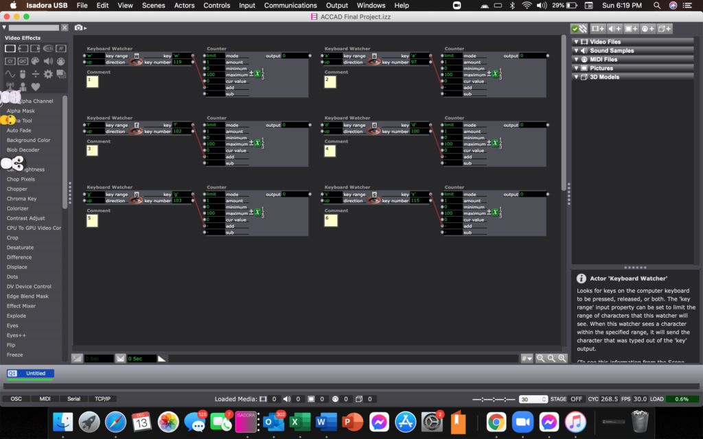
Above is the Isadora patch itself.
I do not have any photos of the box during this cycle, as I forgot to photograph any before moving onto the third cycle. The cycle three file will describe the detailed changes between two and three, for the box.
Cycle 1 – Final Project
Posted: December 13, 2020 Filed under: Uncategorized Leave a comment »With my final project, I wanted to create a box that could be used to track the number of cues called together at once by a stage manager.
In order to do so, I would need a box, electrical paint, conductive thread, wires, and a makeymakey. Once I got everything needed, I began crafting out the measurements to be able to line everything up on the box to allow comfortable sized numbers, and organization to ease use.
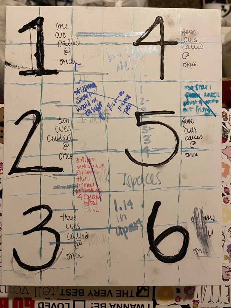
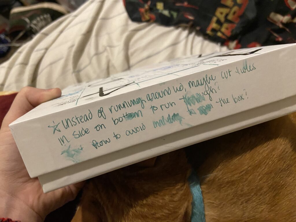


Each of these photos document the original concept for the box, along with all of my added notes for improvement on my next version of the box.
Movement Meditation Room Cycle 3
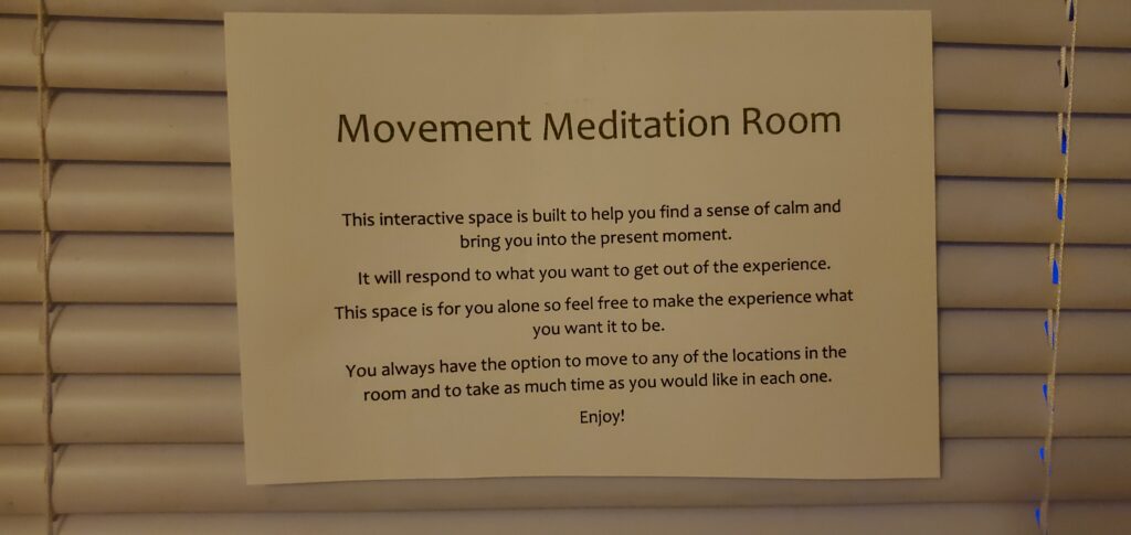
Posted: December 13, 2020 Filed under: Uncategorized Leave a comment »Cycle 3 was a chance for me to figure out how to guide people through the experience. Now that all of the technical elements of the room worked consistently, I needed to think about how to guide people through the space. Originally I thought of putting something on the door that explained the room but I felt that there was a lot of information that wouldn’t make sense until they were in the room itself. So instead I went with an audio guidance system that would tell the user how each element of the room worked as they moved through the space. I still had a brief description on the door that would welcome users into the space:
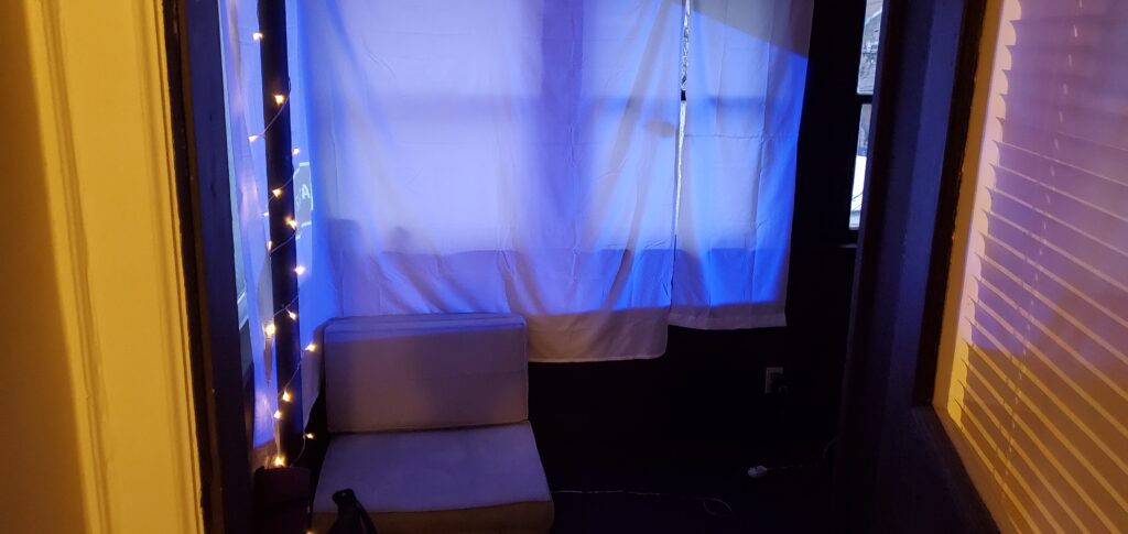
Here is a link where you can watch me go through each of the room’s locations and hear the audio guidance system in action: https://osu.box.com/s/dd5izpw890mx3330r43qgdj3fazkux6i
It is important to note that it was possible for a user to move between locations of the room if they wanted to experience either of the locations again. The triggers were on timers so that the actions of a particular location could restart if the user decided to re-enter the space after leaving it for a certain amount of time. So the amount of time that someone spent in the space was totally up to them and what they wanted to experience.
Unfortunately, due to Covid restrictions, the only people who were able to experience this project was myself and one of my housemates. This is what she said about her experience: “The room offered me a place to reconnect with myself amidst the hectic everyday tasks of life. When in the room, I was able to forget about the things that always linger in the back of my mind, like school work and job applications, and focus on myself and the experience around me. The room was a haven that awakened my senses by helping me unplug from the busy city and allowing me to interact with the calming environment around me.” I thought it was interesting how she felt the technology in the room helped her “unplug” and her feedback gave me further questions about how technology can sometimes hide its influence on our surroundings, and give us experiences that feel “natural” or “unplugged” while also being dependent on technology.
Overall, this cycle felt very successful in providing a calming and centering experience that engaged multiple senses and could be guided by the user’s own interests. I tried to add a biofeedback system that would allow the user to have their heartbeat projected through the sound system of the room, hopefully encouraging deeper body awareness, but my technology was somewhat limited.
I used a contact microphone usually used for musical instruments to hear the heartbeat but because of its sensitivity, it would also pick up the movement of my tendons at my wrist if I moved my hand or fingers at all. Even though I did successfully create a heartbeat sound that matched the rhythm of my heartbeat, the requirement of complete stillness from the elbow down for it to work conflicted too much with goals that were more important to me, like comfort and freedom to move.
In continuing cycles, I might try to build a more robust biofeedback system for the heartbeat and breath. I might also look into the Hybrid Arts Lab locations that might be able to host a Covid-safe installation of the room for more people to experience.
Even if the project itself isn’t able to continue, I do feel I learned a lot about how different kinds of devices interface with Isadora and I have a saved global actor that houses the depth sensor trigger system that I used to structure the room. My realm of possibility has expanded to include more technology and interdisciplinary approaches to creating art. The RSVP cycles that we used to create these final projects has already helped me start to plan other projects. Coming out of this I feel like I have about a dozen more tools in my art toolbox and I am extremely grateful for the opportunity to develop my artmaking skills beyond dance.
Dynamic Light Tracking System Prototype
Posted: December 12, 2020 Filed under: Uncategorized Leave a comment »By: Kenneth Olson
(Iteration 3)
Approach
For this project I wanted to build off what I learned from the previous iteration. In Iteration 2 I utilized the “Eyes ++ Actor” to manipulate objects on a computer screen by using my fingers, a web camera, black tape, and a table top to create an interactive Sci-fi user interface. This time around I wanted to create an even easier, more approachable, way to make objects on a screen move in correlation to how the user moves. A more intractable and abstract system than previous. The system utilizes the “Eyes ++ Actor” and the contrasting qualities of physical light and the void of darkness, with a web camera. The overall system is simple, however, depending on the case usage could result in complicated outputs.
The system works as follows. First, in the middle of a dark room, the user will use their phone flashlight to wave around (the user could be responding to music through dance, or other forms of stimulus that would cause the human body to move freely). Second, A web camera, facing the user, will then feed into Isadora. Third, the web camera output would then connect to the “Eyes ++ Actor” to then affect other objects.
With this system I discovered an additional output value I could utilize. Within Iteration 2 I was limited to only “X” and “Y” values of the “Blob Decoder” coming from the “Eyes ++ Actor” .In iteration 3 I also had “X” and “Y” values to play with (because the light from the flashlight was high enough contrast from the black darkness for the “Eyes ++ Actor” to track) My third output, as a result of using light, was the brightness output of the “Eyes ++ Actor”. Unlike before, in Iteration 2, the size of the object in the tracking area did not change significantly, if at all. However, in Iteration 3 the amount of light shown at the Web Camera would drastically change the size of the object being tracked, resulting in more or less of the tracking area to be filled with white or black. So by using one dynamic contrasting light value as an input to the “Eyes ++ Actor” I was able to affect several different objects in several different ways. This discovery only came about from playing around with the Issadora system.
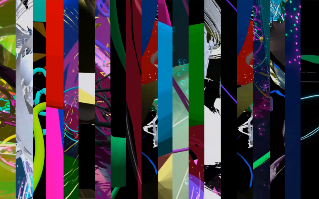
With this dynamic light tracking system, I made ten different vignettes with different interactable objects and videos. Bellow are just a few examples:
Vignette 1
In this scene the blue and purple shapes would change scale with the addition of more or less light.
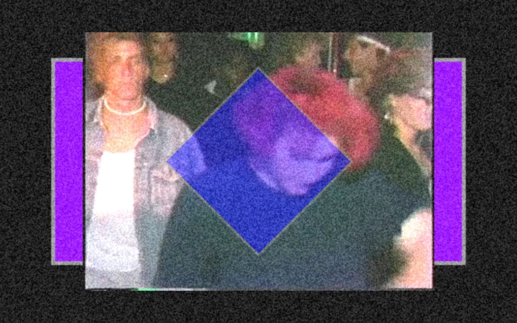
Vignette 2
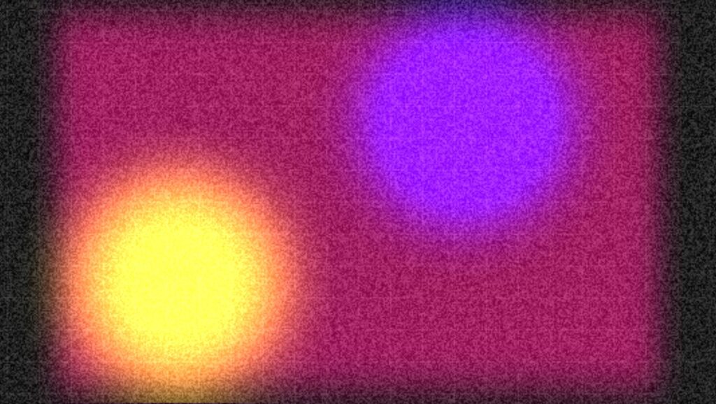
In this scene the two colored circles would move in both “X” and “Y” directions in correlation to the light’s position within the tracking area. And a white grid would appear and overlay the circles with the addition of more light and the grid would fade away with less light.
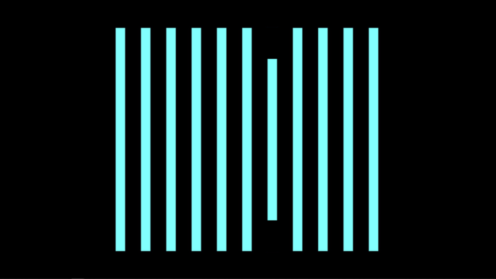
Vignette 3
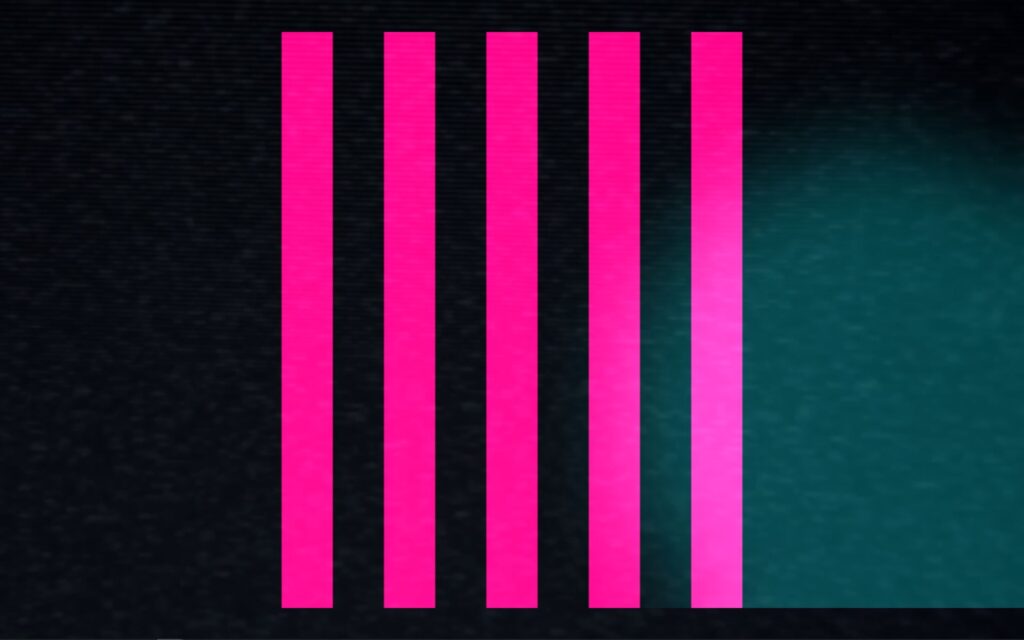
In this scene the pink lines would squash in succession when the light source moves from left to right or from right to left. (this scene was inspired by my iteration 2 project)
Assessment
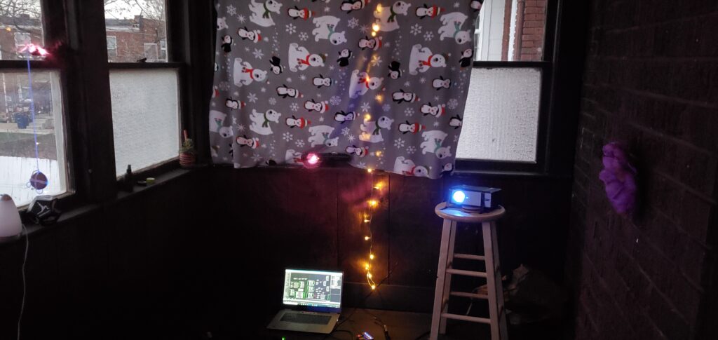
Overall I found this system to be less accurate or less controllable for precise movements, when compared to iteration 2. I could imagine with a more focused amount of light the system would behave better. However, the brightness value output was very responsive and very controllable. I did not try using multiple light sources as an input, but with too much light the system does not function as well. I would love to see this system integrated into a large in person concert or rave with every member of the audience wearing a light up bracelet, or something. But as a party of one, I used a projector as an output device for this system and created a mini rave for one, in my apartment. I used my phone light and also played music from my phone. With even more projectors in the space I could imagine the user would become even more engaged with the system.
Isadora Patch:
Intractable Motion Tracking User Interface Prototype
Posted: December 12, 2020 Filed under: Uncategorized Leave a comment »By Kenneth Olson
(Iteration Two)
Inspiration
I was inspired by science fiction user interfaces (UI) from movies like: “Oblivion” and “Minority Report” and other UI work from the motion designer, Gmunk. I wanted to try and create a real high tech interactable UI system using approachable low tech. This is so others could easily recreate this system. The above Image is the sample inspiration I made inside of Isadora. In the patch, the dots flash on and off, the numbers change, the lines move back and forth, and the circles rotate. Everything in the patch (except for the black grid) was made inIsadora and moved using several “Wave Generator Actors” and “Shape Actors.”
Approach
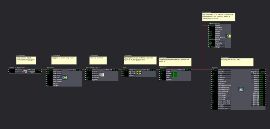
In most of the movies examples of “future UI” The actors are interacting with some sort of black or clear display, and are using their hands as an input to alter or affect the objects on the display. To get Isadora to listen/follow my hands I used the “Eyes ++ Actor,” a web camera, black tape, and a white table top. My goal was to keep the overall system approachable and simple to create, and a web camera with black tape seemed to be the simplest tools for the job.
The system works by: first, wrapping the users index fingers with black tape. Second, set up the web camera in a top down orientation, looking down at the users hands. Third, use a white table top, or a white sheet of paper works great, (this creates a high contracting image for isadora to track). Finally, direct the web camera output into an “Eyes ++ Actor”. From here anything is possible. Depending on lighting and other conditions, I found it helpful to add some extra Isadora Actors to make the system run smoother. (as shown below).
Eyes ++ Actor
The “Eyes ++ Actor” works great for this system, however, results may vary for other people. I was able to track up to three fingers at a time with relative ease. I should also note the “Eyes ++ Actor” works by following the brightest object in the scene, So by using a white table and black taped fingers I needed to turn “inverse” ON in the “Eyes ++ Actor” settings. I also assume this system will also function with a black table/background with white taped fingers. In this scenario you would keep the “inverse” setting to OFF in the “Eyes ++ Actor” settings. Because my hands are so white they blended into the white table easter, but for people with significant darker skin than mine, I would suggest using white tape with a darker table.
Uses and Examples
I used this system three different ways:
1) piano
2) connect the dots
3) multiple sliders.
Piano
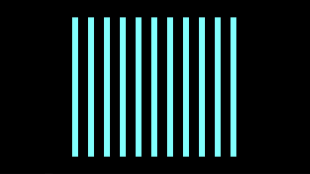
In this system, when I moved my finger, with the tap on it, from left to right or right to left the lines on the screen would shrink. Sound could be added within this system, like a piano note when each line is triggered.
Connect The Dots
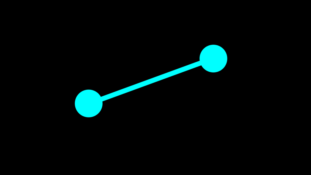
In this system, I used both hands. I have tape on my left and right index finger. The left dot is following my left index finger and the right dot is following my right index finger. The line is being auto generated with the “Lines Actor” and will always follow and connect the two dots together.
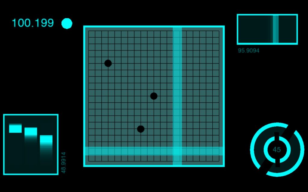
Sliders
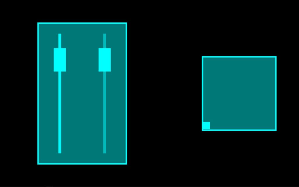
In this system I have two different sliders. The slider on the left controls the horizontal position of the small square found in the box on the right. And the Slider on the right controls the vertical position of the small square. When used together the square can move around within the box. An important feature I wanted to create with these sliders was when one slider was in use the other sider would not move. I accomplished this with the use of the “Panner Actor” to select a specific area of the web camera output to watch. As with the other systems the “Eye’s ++ Actor” was using the entire web camera output to read and follow my taped finger. However, by using the “Panner Actor” I could scale down what the “Eye’s ++ Actor” could see, this focused the web camera output to a specific range. Meaning the “Eye’s ++ Actor” could only see my finger within a specific area of the table.
Assessment
With the time I had I accomplished what I set out to do by creating a hand controlled science fiction user interface. I would have liked to been able to put all of the systems I created for this project together, however, my computer wouldn’t allow such things to happen. For future iterations I would like to play with scale more. Perhaps replace the finger with a human body and have the “Eye’s ++ Actor” follow the human form. The “Eye’s ++ Actor” did work most of the time, but I did lose the tracking of my finger sometimes causing the visuals in the “Projector Actor” to “glitch out” not sure what was causing this issue weather it was the web camera, the “Eye’s ++ Actor”, or maybe the several other actors I used to edit the webcam footage. I would also like to find a way for the user to be touching the objects being affected in Isadora. Meaning, the user could touch the computer screen or a projection screen and the objects being projected would look like they were directly following the users hands on the screen, instead of the objects indirectly following the movement of the hands on the white or black table.
Isadora Patch:
Tara Burns – “a canvasUnbound” (Cycle 3)
Posted: December 10, 2020 Filed under: Uncategorized 1 Comment »Goals
*To have panels that disappear when triggered
*To have that reveal an underlying theme/movie
*To use the Oculus Quest as the reveal movie
Challenges
*Everything worked in my office and then when changing to the basement I had to add a few more features in order for it to work. I think the version it ended up at will hopefully be more able to travel with slight modifications. *It is very difficult to create an interactive system without a body in the space to test.
*The Oculus Quest doesn’t work without light, so without directional light I did get that working but you couldn’t see the projection. So in the final video I opted to just use a movie, knowing that it did work is good enough for me at this point and when/if I’m able to use directional light that doesn’t effect the projection we can try it again then. Alternately the positive of this is that I can interact with the system more, if painting in VR, I can’t see when and if I make the panels go away and where I need to dance in order to make that happen.
Moving forward
I’d would put this as big as possible and flip the panels to trigger on the same side as myself (the performer). Take some time to rehearse more inside the system to come up with a score with repetition and duration that allowed for people to see the connections if they are looking for it. Perhaps use the VR headset if that works out, but I am also ok with painting and then recording (the recording is the score that corresponds when the dance) a new white score specific to the space I am performing in to then use in performance. If large enough I think it would be easy to see what I am triggering when they are on the same side as me. In my basement, I chose to trigger the opposite side because my shadow covered the whole image.
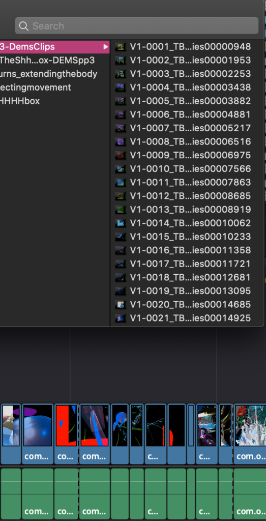
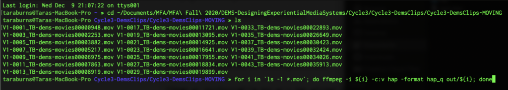
I converted all the movies to the HAP codec and it cut my 450% load in Isadora to 140%. This decision was prompted not because it was crashing anymore but it was freezing when I would click through tabs.
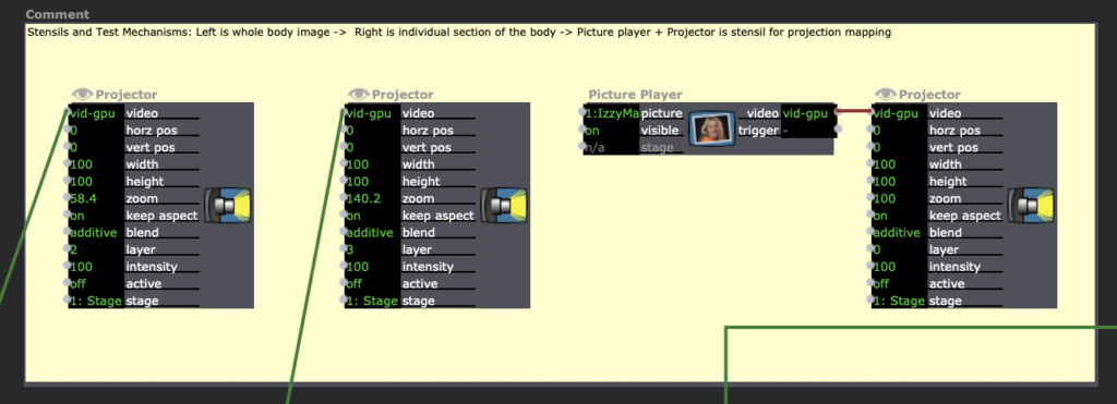
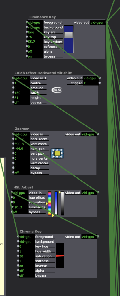
Cycle Project 3
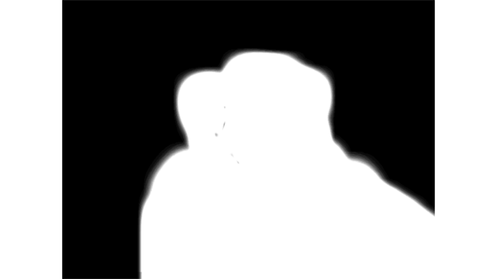
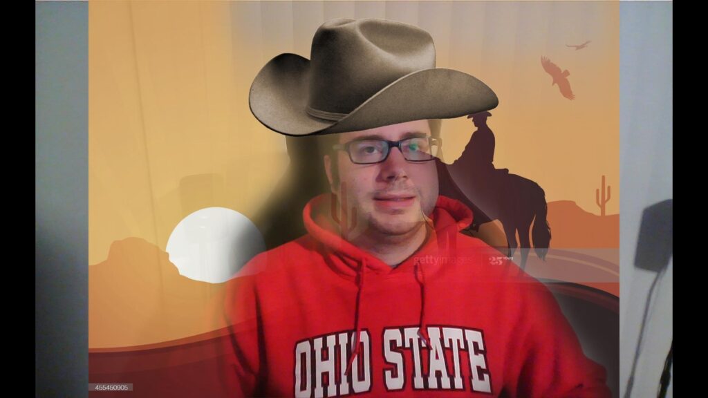
Posted: December 10, 2020 Filed under: Uncategorized Leave a comment »In my Cycle 3 project, I wanted to get a bit better filter with a harder edge to edit out the background of the images. Alex and I worked together and added some TT Sharpen effects, Gauzian blur and TT Sorbel Edge Detection. These filters stacked on top of each other allowed me to get my entire body cut out from the background. I think if I had something like a green screen in the background, the effect would be even more precise.
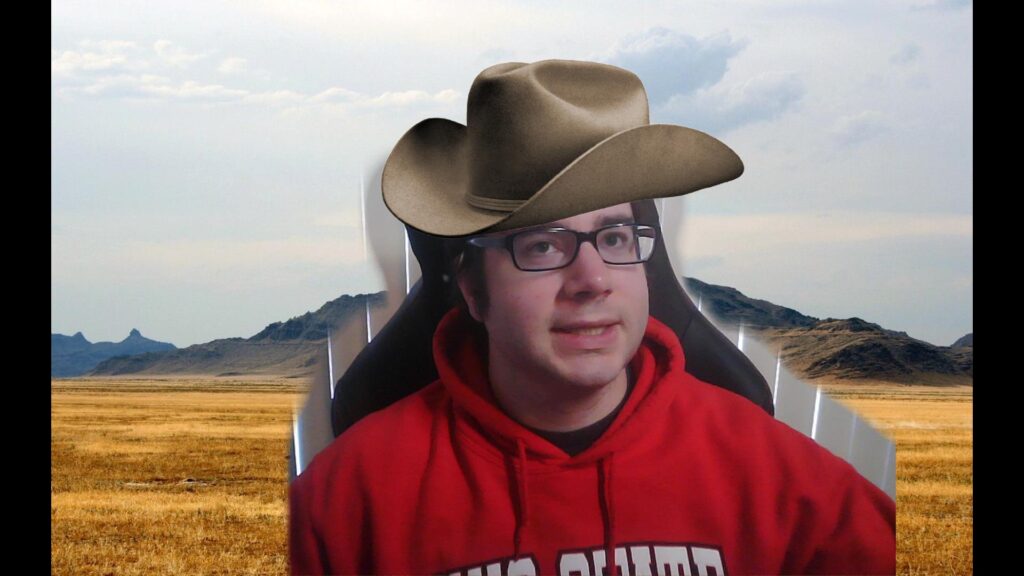
My major goal for the third iteration of the project was adding some things to make the user experience more interesting. I added some sound effects when buttons were pushed on the makey makey, as well as some short animations that would play after the user took a picture with a hat on.
I also added a third environment, which is a party scene. Overall, this project allowed me to synthesize many of the tools we were working with during the class. I used the makey makey as the interface. I also used the Leapmotion hand sensor to allow users to rotate and resize an image.
Much of my work on this project involved compositing, as I used the depth camera to capture the image of the user as well as the filter that would allow for the removal of the background.
If I were to continue on this project further, I would want to take the composited image of the user with the hat and put them into a game like situation, perhaps something like some of the games that came with the game boy camera software. I found that I really enjoyed designing experiences that users would interact with and trying to figure out what would make them clear and easy to use.
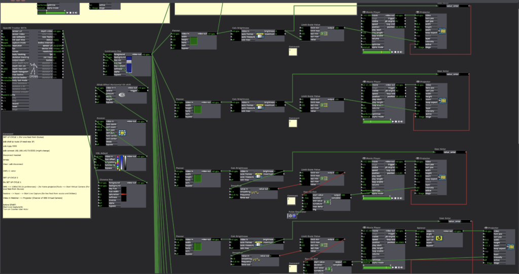
Cycle 3 Isadora patch
https://1drv.ms/u/s!Ai2N4YhYaKTvgbYSo1Tsa-MdTV2ZGQ?e=EmjBNh
This is a recording of me showing the different parts of my cycle 3 project
https://1drv.ms/u/s!Ai2N4YhYaKTvgbYctMNYMgWOb7P3Sg?e=5hRoqY
Cycle Project 2
Posted: December 10, 2020 Filed under: Uncategorized Leave a comment »As the next step in the photo booth project, I wanted to switch from using my webcam to the Orbecc Astra camera so that I could capture depth data while I was capturing the image. With the depth data, I would use a luminance key to filter out the background portion of my image.
One of the difficult parts of this project was the resolution of the Astra camera. It incorrectly detected some parts of my face, so they became transparent when run through the luminance key. In order to combat this, I added a gauzian blur, but it was not quite the tight filter I was looking for with my project.
https://1drv.ms/u/s!Ai2N4YhYaKTvgbYWfqACckMc8dOFkg?e=wsLF3P
This is a link for my code for cycle 2
https://1drv.ms/u/s!Ai2N4YhYaKTvgbYbCQq_7ZQ6ZIghtg?e=CXGBWk
This is a link to a video file of my cycle 2 presentation.