Cycle 3: Puzzlr Final
Posted: December 12, 2022 Filed under: Uncategorized Leave a comment »Introduction
The ending of this project was particularly frustrating because I ended up getting COVID the last week of classes. Yes if you’re reading this 20 years in the future, COVID was a terrible virus that crippled most of the planet in 2020, and we are now living with it every day. Because of this, I was not able to present my final prototype to the class, so a part of this documentation post will include a short video demo on how my game works!
The final project was a great prototype that I am very proud of. After refining some of the cable setups and improving the stability of the Makey-Makey board, I was able to get most of the contacts working. Because of the way I glued and reinforced the wires, some of the contacts cross over, so some will activate more than 1 “keystroke” on the Makey-Makey. Combining this with the digital experience I created on Isadora yielded a pleasing result that was an excellent insight into how different microcontroller boards work.
Reflecting on the Build Process
Building and testing Puzzlr was no easy process. It involved a lot if iteration through different laser-cut prototypes and testing scenarios. I learned how to wire-up and configure the Makey Makey within Isadora, and had to design a circuit system that would work with the Puzzle style.
The first wooden prototype allowed me to test the setup and whether the puzzle would be hard for others to solve. It turned out to be a n excellent learning moment because I ended up adjusting the thickness to actually fit the wires, and even learned that I had to flip the puzzle pieces to get the correct engravings.
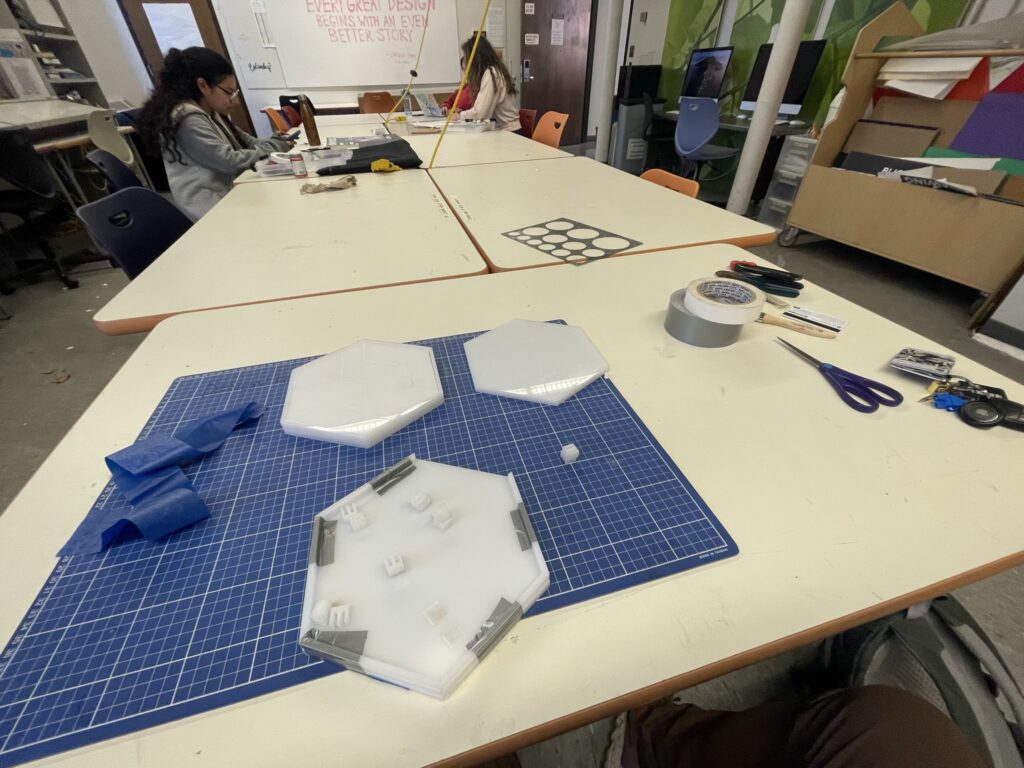
The second and final prototype involved laser-cutting the puzzle out of white acrylic. Then I sanded everything down, cleaned it up, and put it together with duct tape. I would have glued it together but I needed constant easy access to the wire housing to make adjustments and improvements. Another hurdle at this stage was sanding down the circuit clips that hold the wires together. They were initially too tall and ended up poking through the holes; I had to sand them down so they would remain flush with the upper level. By using tin foil, foil tape, glue, and duct tape, I was able to put everything together and get the circuit completed.
How the Game Works
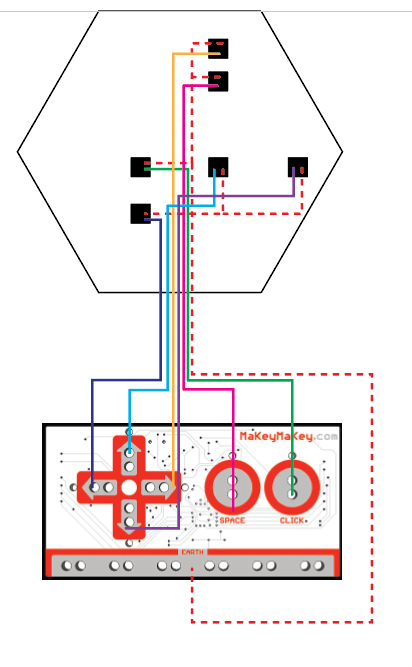
Here is a picture of the actual schematic I created for the puzzle board. The goal of the game is simple: get the pieces onto the board and in the right spots. Each puzzle piece has a piece of metal foil tape underneath it that corresponds to the black squares on the schematic. When the piece makes contact with the board it completes each circuit by closing the loop between the ground and input wires. Each contact corresponds to a certain input on the Makey-Makey, and when activated will relay a keystroke to the computer.

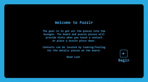
Starter Screen
Instruction Screen

Game screen. As pieces get placed on the board, they begin appearing here. If they are removed from the contact, the piece will disappear a few seconds after it is no longer receiving an input signal.

Win screen
Video Demo
Reflecting on the Project
I really enjoyed this exploratory project because it allowed me to experiment with something I was considering for my thesis. The Makey-Makey system is really unique but has it’s issues with more robust and complex applications. If I were to change anything about this project, I would have spent some time learning how to solder so the connections could be a little stronger. I will be applying the things I learned during this project when creating my own microcontroller input methods for my thesis in the future!