Tactile Pavillion
Posted: August 28, 2018 Filed under: Uncategorized Leave a comment »Last Thursday I was unable to make it to class- I wanted to share with all of you what the project I was working on at the time!
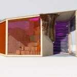
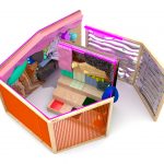
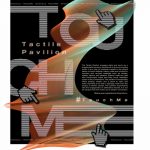
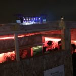
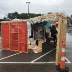
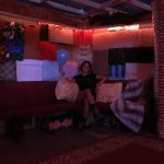
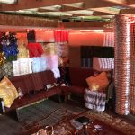
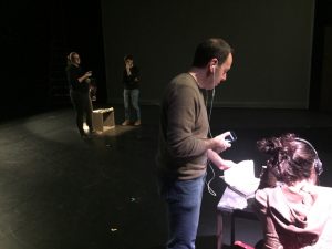
As the poster states, the Tactile Pavilion engages sight and touch as a supplemental sensory experience to the surrounding music festival. It is a way to immerse oneself in the playful nature of found objects. Interior walls are covered in recycled and re-used materials such as textiles, metals, and plastics. Exterior walls are clad with construction mesh and bare wood. Insulation oozes at the connections. The pavilion’s functionality offers seating, shelter, and a place to relax and reset- devoting a full wall to signage made from the scraps of interior panels. The pavilion experiments with the engagement of alternative senses. It is not an escape from the music, but a deeper connection.
There will be more images/ descriptions about the project that you can check out at my personal site- https://marcd.co
2018 Readings
Posted: August 21, 2018 Filed under: Uncategorized Leave a comment »Here are links to the readings:
Few believe the world is…gnition.
– ResearchGate experiential learning – toolwire
EMS – Applications, motivating ideas, AI, summary
An Arts, Sciences and Engineering Education and Research Initiative for Experiential Media
http://faculty.georgetown.edu/irvinem/theory/Manovich-LangNewMedia-excerpt.pdf
Cycle 1 Reflection-Mystery House
Posted: December 11, 2017 Filed under: Kelsey Gallagher, Uncategorized Leave a comment »Mystery House
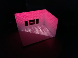
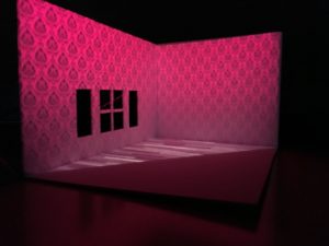
For my first showing of my system, I had built a 1″=1′ scale model of a room with 2 walls. 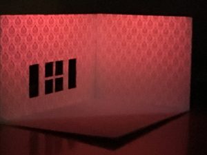
This section of a room was projection mapped with one pico projector through Isadora. Insolently when I set up my Isadora session it was not registering my Key so I lost my file from this session, leaving me to remake it for the final presentation.
The few things I was able to show during this presentation were
-Widow Effects such as a moon with clouds or a storm
-The lights turning on or off
The feedback I received from my peers was enlightening.
It was suggested that I make an interface for the viewer to play with rather than it be presentational. Also that audio would add greatly and to think about including headphones.
Overall my first round achieved what I wanted and even more I was given valuable feedback.
Cycle 1 Reflection: Looking Across, Moving Inside
Posted: December 10, 2017 Filed under: Uncategorized Leave a comment »Cycle 1 was a chance to pivot in terms of how I was approaching this project. At this point I had a working understanding of what the installation was going to do, but performing it in front of my colleagues revealed methodological challenges.
Specifically, the rotoscoping process I was using to remove dancers from the background of prerecorded videos was far too time-consuming. This was how the process worked:
- Aquire short films of dancers performing or rehearsing (gathered from friends or shot myself)
- Import videos into After Effect
- Use the AF rotoscoping tool to begin cutting out each dancer from the video on their own composition layer. The rotoscoping tool attempts to intelligently locate the edge of the object you are trying to isolate in each frame, but its success is based on the contrast of the object from the background, how fast the object is moving, and how many parts of the object move in different direction. A dancer in sweats against a white wall with many other objects around is obviously not a good candidate for predictive rotoscoping. Therefore, each frame must be cleaned up. Additionally, when dancers pass in front or behind each other, or make contact, it is virtually impossible to separate them.
- Once each frame is cleaned up, they are exported to a standalone, alpha-channeled video
This is very short test I did with a live and rotoscoped dancers that represents at least eight hours of rotoscoping. Looks good, but incredibly inefficient.
Switching to a green screen capture model should make this process more efficient, allowing me to spend more time on the actual interaction of the video and the live dancer and less on simply compiling the required media. Additionally, the resolution and depth of field of the Kinect was too low and shallow for the live participant to interact with the prerecorded dancer in a meaningful way. Alex suggested upgrade to the Kinect 2, which has increased resolution and depth of field.
Attached is the initial Isadora patch for placing a silhouette of a live person alongside a video:
https://www.dropbox.com/s/54qn8bfmoc2o5hg/Cycle-1.izz?dl=0
Final Project: Looking Across, Moving Inside
Posted: December 10, 2017 Filed under: Final Project, Uncategorized Leave a comment »Looking Across, Moving Inside
What are different ways that we can experience a performance? Erin Manning suggests that topologies of experience, or relationscapes, reveal the relationships between making, performing, and witnessing. For example, the relationship between writing a script or score, assembling performers, rehearsing, performing, and engaging the audience. Understanding these associations is an interactive and potentially immersive process that allows one to look across and move inside a work in a way that witnessing only does not. For this project, I created an immersive and interactive installation that allows an audience member to look across and move inside a dance. This installation considers the potential for reintroducing the dimension of depth to pre-recorded video on a flat screen.
Hardware and Software
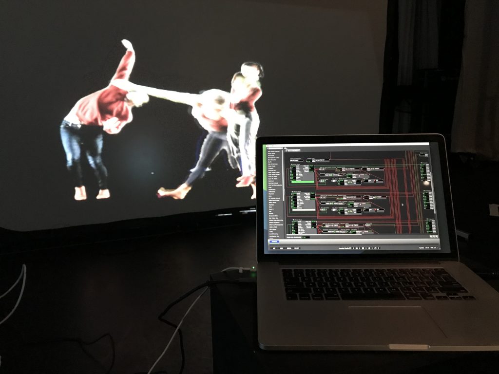
The hardware and software required includes a large screen that supports rear projection, a digital projector, an Xbox Kinect 2, a flat-panel display with speakers, and two laptops—one running Isadora and the other running PowerPoint. These technologies are organized as follows:
A screen is set up in the center of the space with the projector and one laptop behind it. The Kinect 2 sensor is slipped under the screen, pointing at an approximately six-foot by six-foot space delineated by tape on the floor. The flat-panel screen and second laptop are on a stand next to the screen, angled toward the taped area.
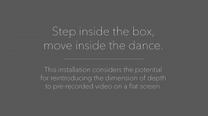
The laptop behind the screen is running the Isadora patch and the second laptop simply displays a PowerPoint slide that instructs the participant to “Step inside the box, move inside the dance.”
Media
Generally, projection in dance performance places the live dancers in front of or behind the projected image. One cannot move to the foreground or background at will without predetermining when and where the live dancer will move. In this installation, the live dancer can move to up or downstage at will. To achieve this the pre-recorded dancers must be filmed singly with an alpha channel and then composited together.
I first attempted to rotoscope individual dancers out from their backgrounds in prerecorded dance videos. Despite helpful tools in After Effects designed to speed up this process, each frame of video must still be manually corrected, and when two dancers overlap the process becomes extremely time consuming. One minute of rotoscoped video takes approximately four hours of work. This is an initial test using a dancer rotoscoped from a video shot in a dance studio:
Abandoning that approach, and with the help of Sarah Lawler, I recorded ten dancers moving individually in front of a green screen. This process, while still requiring post-processing in After Effects, was significantly faster. These ten alpha-channeled videos then comprised the pre-recorded media necessary for the work. An audio track was added for background music. Here is an example of a green-screen dancer:
Programming
The Isadora patch was divided into three main function:
Videos
The Projector for each prerecorded video was placed on an odd numbered layer. As each video ends, a random number of seconds passes before they reenter the stage. A Gate actor prevents more than three dancers from being on stage at once by keeping track of how many videos are currently playing.
The Live Dancer
Brightness data was captured from the Kinect 2 (upgraded from the original Kinect for greater resolution and depth of field) via Syphon and fed through several filters in order to isolate the body of the participant.
Calculating Depth
Isadora logic was set up such that as the participate moved forward (increased brightness), the layer number on which they were projected increased by even numbers. As they moved backwards, the layer number decreased. In other words, the live dancer might be on layer 2, behind the prerecorded dancers on layers 3, 5, 7, and 9. As the live dancer move forward to layer 6, they are now in front of the prerecorded dancers on levels 3 and 5, but behind those on levels 7 and 9.
Download the patch here: https://www.dropbox.com/s/6anzklc0z80k7z4/Depth%20Study-5-KinectV2.izz?dl=0
In Practice
Watching people interact with the installation was extremely satisfying. There is a moment of “oh!” when they realize that they can move in and around the dancers on the screen. People experimented with jumping forward and back, getting low the floor, mimicking the movement of the dancers, leaving the stage and coming back on, and more. Here are some examples of people interacting with the dancers:
Devising Experiential Media from Benny Simon on Vimeo.
Devising Experiential Media from Benny Simon on Vimeo.
Devising Experiential Media from Benny Simon on Vimeo.
Future Questions
Is it possible for the live participant to be on more than one layer at a time? In other words, could they curve their body around a prerecorded dancer’s body? This would require a more complex method of capturing movement in real-time than the Kinect can provide.
What else can happen in a virtual environment when dancer move in and around each other? What configurations of movement can trigger effects or behaviors that are not possible in a physical world?
Pressure Project 3: Trailblazing
Posted: December 4, 2017 Filed under: Calder White, Paper & Pen, Pen and Pencil Games, Pressure Project 3, Uncategorized Leave a comment »For our third Pressure Project, our prompt was to take a pen & paper game and combine it with another game to make a delightfully replayable hybrid that had no more than 5 rules and did not require the creator’s verbal or gestural intervention. I love to play card games, and especially drinking games involved with cards, and so I decided to figure out a way in which I could revamp one of my favourite drinking card games — Ride the Bus — to suit this assignment.
For those who don’t know, Ride the Bus is a drinking game played with two people. The dealer lays out five cards and flips the first one. The second player then goes through a sequence of questions guessing the nature of the proceeding cards in this order:
- Is the second card higher or lower than the first card?
- Is the third card inside of (between) or outside of the first two cards?
- Is the fourth card red or black?
- What is the suit of the last card?
The catch is this: if at any point the second guesser makes an incorrect guess, they have to take a drink, a new set of five cards is dealt, and the game restarts. The player only wins once they “ride the bus” to the end.
Taking some inspiration from tic-tac-toe and Connect 4, I was curious about how Ride the Bus could function if placed in a grid. I decided that the cards would be set up in a 5×5 grid and this would become a game about which player — the dealer or the guesser — could collect the most cards by the end. Instead of having to drink for guessing a card incorrectly, an incorrect guess simply signaled the end of a player’s turn and therefore a stunted chance at collecting more cards.
The instruction sheet of my hybrid game can be found here: ACCADTrailblazing
In the end, this game reminded me a lot of afternoon’s spent at my Baba’s house playing War for hours. Although perhaps not the most stimulating for adults, Trailblazing could easily be an entertaining children’s or family game, and definitely gets more fun the more you play it!
Cycle 1 Presentation – here4u
Posted: November 28, 2017 Filed under: Calder White, Final Project, Uncategorized Leave a comment »For my final project in DEMS, titled here4u, I’m working to tell a non-linear narrative about a long distance platonic relationship between a mother and a son. The story is told mainly through text messages, voicemails, and journal entries and photographs (both physical and digital), unlocked via QR codes scattered throughout the installation. My inspiration comes from an extremely personal place as I have been in this very situation for the past four years of my undergraduate career, and my drive for this project stems from an artistic desire for transparency between creator/performer and the audience. Through this project, I am opening myself up to the audience — using actual voicemails and texts between my mother and I and actual entries from my journal — to tell a story about distance, loneliness, belonging, misinformation, struggle, and coming of age. I am doing all of this in the hopes that my “baring it all” can open a dialogue about connection and relation between myself and the people experiencing this installation, as well as between the visitors to the space.
In the first cycle presentation, I organized two desk spaces diagonal to each other in the Motion Lab, one being the “mother” space and the other being the “son” space. The mother space has various artifacts that would be found on my mom’s desk at home: note pads with hand-written reminders, prayer cards and rosaries from my Baba, and a film photograph from the cottage that my mom and I used to live in. Spread within the artifacts are QR codes that include worried voicemails from my mom about suspicious activity on campus, texts from her to me asking where I’ve been, and links to screen recordings of our longer text conversations.
Across the room stands the son space, a much less organized desk with worn and filled daily planners, books dealing with citizenship theory, journals open to personal entries, and crumpled to-do lists. The QR codes here lead to first-person videos of protests, an online gallery of silhouetted selfies, and voicemails apologizing for taking so long to respond to my mom.
In the creation of this project, I am dredging up a wealth of emotions from my time in Columbus and pinning it to a presentation that I hope won’t feel like a performance. That being said, I realize that in it’s presentational nature, there are certain theatrical elements that need to be considered and addressed. With the first cycle showing, I learned very quickly how individual an experience this is. In order to get the most out of the QR codes — particularly the voicemails — the audience members must wear headphones, which immediately isolates them into their own world and deters connection with other audience members during their experience. In my attempt for creating a feeling of loneliness, I would say this was a success.
I received a wealth of feedback on which aspects of both spaces worked and which didn’t, and agreement on the most powerful aspects of the story-telling being the voicemails and texts was unanimous due to the emotion heard in the voice. At the suggestion of Ashlee Daniels Taylor, I will be working to generally increase the amount of material in the space so that there is more to look through and find in the QR codes. This works towards another one of my goals with the narrative, which is to engender the sense of a story without the need for the audience member to find every single piece of the puzzle, amplifying individual experience within the installation.
For my second cycle, I have been working towards the generation of more material to be found and directing the experience moreso than in my first presentation. Without any sort of guidance using vocal, lighting, or other cues, the first presentation invited viewers to find their own way through the installation which, although was fun for me to watch and hear how different people pieced together the experience for themselves, led to awkward successive QR codes (being too similar or repetitive), a desire for more direction, and an undefined ending to the experience. I will be working with some theatrical lighting to guide the viewers in a more predetermined path through the space.
The emotional feedback that I received after the first presentation has inspired me to push forward with this project’s main intentions and to develop this experience has honestly and authentically as possible. The tears and personal relations shared in our post-presentation discussion proved to me the value in making oneself vulnerable to their audience and I intend to lean into this for the second cycle presentation.
Pressure Project 3
Posted: November 7, 2017 Filed under: Kelsey Gallagher, Uncategorized Leave a comment »I was super excited to do pressure project 3. I have a lot of background in playing tabletop/board games so I found this only challenging in the limitations. I knew immediately I wanted to use a game my friends and played many times, which is similar to pictionary and telephone mixed together. I just needed to find another game to meld with it. I knew, because of my large collection of dice, I wanted to use dice.
I did a bunch of google searches and pintrest searches for dice games. After reading 3 or 4 I found gambling game that was interesting and alterable.
Then I just let my own creative juice run to create a narrative story that involves both of those two games.
This was the final project.
The Unfortunate Adventurers and the Wishing Well
Kelsey Gallagher
Pressure Project 2: The Tell Tale Heart
Posted: November 7, 2017 Filed under: Kelsey Gallagher, Uncategorized Leave a comment »Pressure Project 2
So for this project my personal goal was to pull a physical response from my audience. I chose Edgar Allan Poe’s Tell Tale Heart because it is one of my most favorite stories from my childhood. It also is a story that is easily told with just audio. My first choice was to try and tell The Tale of the Beetle and the Bard story of the three brothers, but the concept was frustrating so I chose to switch stories.
I first scoured the internet for a creepy underscore that could set the tone of the minute piece. Eventually I found on I liked and I exported it.
After finding this I used FreeSound.org to find the correct sound effects to create the experience. Through the use of Audacity software I created one file that told the story.
This the end product.
Kelsey Gallagher
PP3 – Aut ’17
Posted: October 10, 2017 Filed under: Uncategorized Leave a comment »
Pen & Paper + (LEVEL 3 Pressure Project)
Context:
According to wikipedia, examples of Pen & Paper Games include ” Tic-tac-toe, Sprouts, and Dots and Boxes. Other games include: Hangman, Connect 5, M.A.S.H., Boggle, Battleships, Paper Soccer, and MLine.”
Assignment:
Choose a known (at least to you) pen & paper game*.
Combine it with another game. The second game can be another pen and pencil game, a card game, a dice game, or a interactive projection.
You have no more than 5 hours to complete this project. (Not including research.)
*Please feel free to keep things simple. Yet, here are some more adventurous examples:
- http://zenseeker.net/BoardGames/PaperPenGames.htm ,
- http://www.thegamesjournal.com/articles/GameSystems4.shtml,
Basic Limitations:
- new game can have no more than 5 rules
- a novice player must be able to play without your verbal or gestural intervention. (provide an instruction sheet with the rules.)
Basic Level 3 Achievements :
- Fun to play
- Game is delightfully repayable
Legendary Achievements:
- includes a plot driven narrative
- includes an interactive projection
