Cycle Project 1
Posted: December 10, 2020 Filed under: Uncategorized Leave a comment »For this project I wanted to synthesize some of the work I had done on my previous projects in the class. I wanted to create a kind of photobooth. Users would operate the booth by the makey makey and then Isadora would capture a webcam image of the user. From there the user can select different environments to add hats. For this iteration of the project, I offered a choice between a Western theme and a space theme.
After selecting the desired theme, the users could adjust the size of the hat by pressing a button on the makey makey interface. From there, they could use the Leapmotion controller and reposition and rotate the hat as well as resizing it.
One of the most difficult parts of this project for me was figuring out the compositing using virtual stages. Additionally, I spent a lot of time trying to find ways to make the prompts (which appeared over the image) disappear before the image was taken.
This is a link to my code for the project.
https://1drv.ms/u/s!Ai2N4YhYaKTvgbYVl0LiupCRh2PFdg?e=wuKpZm
Here is the link for my class presentation.
https://1drv.ms/u/s!Ai2N4YhYaKTvgbYaMqgJRuOsmjBMog?e=rDAOMd
Depth Camera CT Scan Projection System
Posted: December 5, 2020 Filed under: Uncategorized Leave a comment »by Kenneth Olson
(Iteration one)

What makes dynamic projection mapping dynamic?
Recently I have been looking into dynamic projection mapping and questioned what makes dynamic projection mapping “Dynamic”? I asked Google and she said: Dynamic means characterized by constant change, activity, or progress. I assumed that means for a projection mapping system to be called “dynamic” something in the system would have to involve actual physical movement of some kind. Like the audience, the physical projector, or the object being projected onto. So, what makes dynamic projection mapping “dynamic” well from my classification the use of physical movement within a projection mapped system is the separation between projection mapping and dynamic projection mapping.
How does dynamic projection mapping work?
So, most dynamic projection systems use a high speed projector (meaning a projector that can project images at a high frame rate, this is to reduce output lag). Then an array of focal lenses and drivers are used (to change the focus of the projector output in real time). A depth camera (to measure the distance between the object being projected onto and the projector) and then a computer system with some sort of software to allow the projector, depth camera, and focusing lens to talk to each other. After understanding the inner workings of how some dynamic projection systems work I started to look further into how a depth camera works and how important depth is within a dynamic projection system.
What is a depth camera and how does depth work?
As I have mentioned before, depth cameras measure distance, specifically the distance between the camera and every pixel captured within the lens. The distance of each pixel is then transcribed into a visual representation like color or value. Over the years depth images have taken many appearances based on different companies and camera systems. Some depth images use gray scale and use brighter values to show objects closer to the camera and darker values to signify objects further in the distance. Each shade of gray would also be tied to a specific value allowing the user to understand visually how far something is from the depth camera. Other systems use color, while using warmer versus cooler colors to measure depth visually.

How is the distance typically measured on an average depth camera?
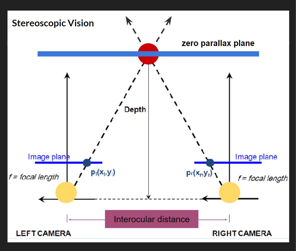
Basically most depth cameras work, the same way your eyes create depth through “Stereoscopic Vision”. For this Stereoscopic Vision to work you need two cameras (or two eyes) in this top down diagram (pictured above), the cameras are the two large yellow circles and the space between them is called the interocular (IN-ter-ocular) distance. This distance never changes, however, this ratio needs to be at a precise distance because if the interocular distance is too close or too far apart the effect won’t work. On the diagram the dotted line shows the cameras are both looking at the red circle. The point at which both camera sight lines cross is called the zero parallax plane, and on this plane all objects are in focus. This means every object that lives in front and behind the zero parallax plane is out of focus. Everyone at home can try this, If you hold your index finger a foot away from your face, and look at your finger, everything in your view, except your finger, becomes out of focus, and with your other hand slid it left and right across your imaginary zero parallax plane, with your eyes still focused on your finger you should notice your other hand is also in focus. There are also different kinds of stereotypes, another common type is Parallel, on the diagram, the two parallel solid lines coming from the yellow circles point straight out. Parallel means these lines will never meet and also mean everything will stay in focus. If you look out your window into the horizon, you will see everything is in focus, the trees, buildings, cars, people, the sky. For those of us who don’t have windows, Stereoscopic and parallel vision can also be recreated and simulated inside of different 3D animation software like Maya or blender. For those who understand 3D animation cameras and rendering, if you render an animation with parallel vision and place the rendered video into Nuke (a very expensive and amazing node and wires based effects and video editing software) you can add the zero parallax plane in post. This is also the system Pixar uses in all of its animated feature films.

Prototyping
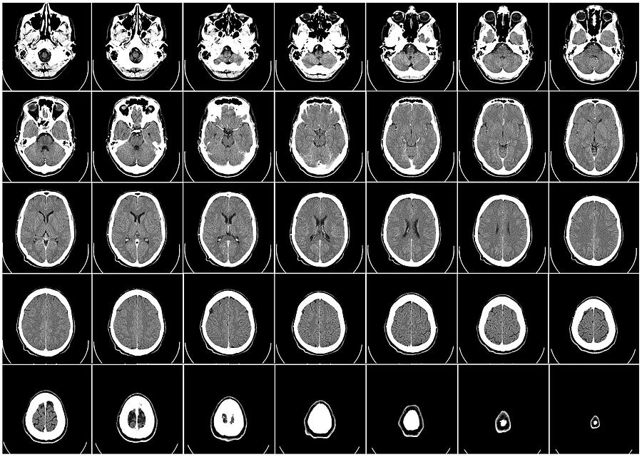
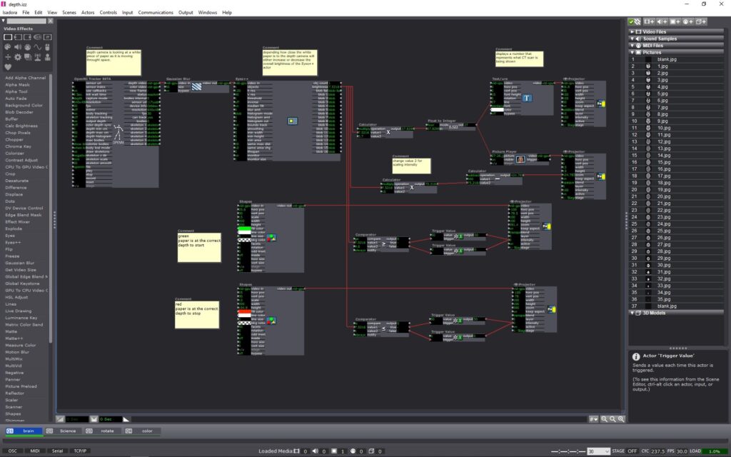
After understanding a little more about how depth cameras work I decided to try and conceive a project using an Astra Orbbec (depth camera), a pico projector (small handheld projector), and Isadora (projection mapping software). Using a depth camera I wanted to try and prototype a dynamic projection mapping system, where the object being projected onto would move in space causing the projection to change or evolve in some way. I ended up using a set of top down human brain computed tomography scans (CT scans) as the evolving or “changing” aspect of my system. The CT scans would be projected onto regular printer paper held in front of the projector and depth camera. The depth camera would read the depth at which the paper is at in space. As the piece of paper moves closer or further away from the depth camera, the CT scan images would cycle through. (above is what the system looked like inside of Isadora and below is a video showing the CT scans evolving in space in real time as the paper movies back and forth from the depth camera) Within the system I add color signifiers to tell the user at what depth to hold the paper at and when to stop moving the paper. I used the color “green” to tell the user to start “here” and the color “red” to tell the user to “stop”. I also added numbers to each ST scan image so the user can identify or reference a specific image.
Conclusion
The finished prototype works fairly well and I am very pleased with the fidelity of the Orbbec depth reading. For my system, I could only work within a specific range in front of my projector, this is because the projected image would become out of focus if I moved the paper too far or too close relative to the projector. While I worked with the projector I found the human body could also be used inplace of the piece of paper, with the projected image of the SC scans filling my shirt front. The projector could also be projected at a different wall with a human interacting with the depth camera alone, causing the ST scans to change as well. With a more refined system I can imagine this could be used in many circumstances. This system could be used within an interactive medical museum exhibit, or even in a more professional medical setting to explain how ST scans work to child cancer patients. For possible future iterations I would like to see if I could incorporate the projection to better follow the paper, having the projector tilt and scale with the paper would allow the system to become more dynamic and possibly more user friendly.