Cycle 3
Posted: December 15, 2025 Filed under: Uncategorized Leave a comment »I somehow managed to get through cycles 1-2 without actually doing anything with Isadora or other technology. Although I learned a lot, I needed to include the “MES” in DEMS. And what a mes I made!
Perhaps the mist valuable topic explored in my Cycle 2 was the part about proximity. What is the distance between a users actions and the result of that action? Is it immediate like a typewriter, or further away like a garage door opener? Cycle 2 focused on proximity from the point of view of the user, but what about from the perspective of the tech itself? What is the user is unaware that they are interacting with technology at all? This is what Cycle 3 explored. How does a machine detect its own proximity to a user.
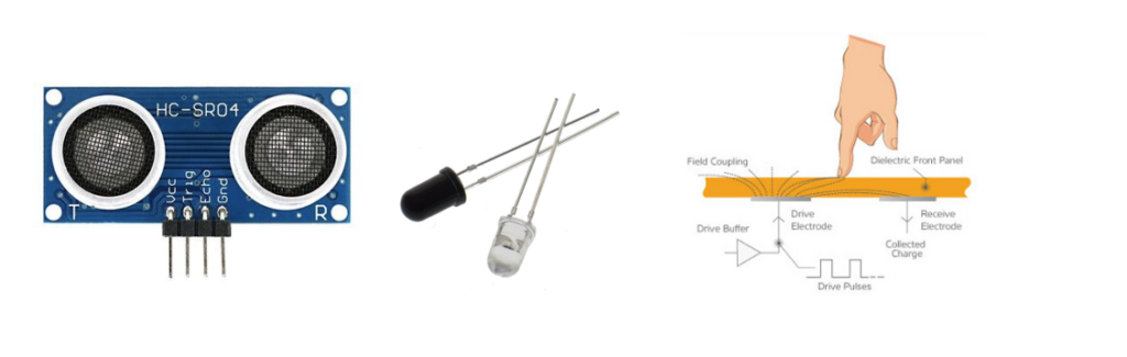
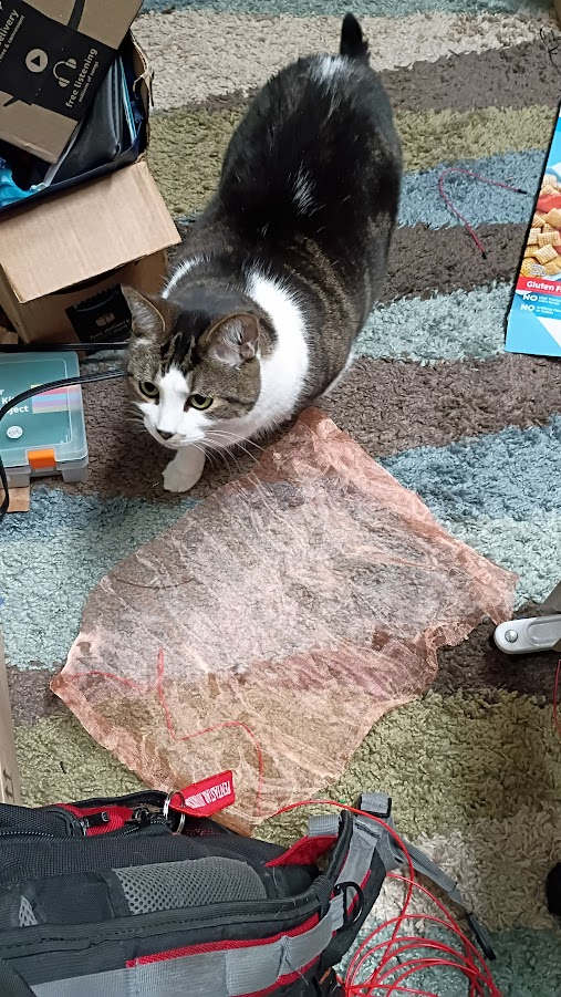
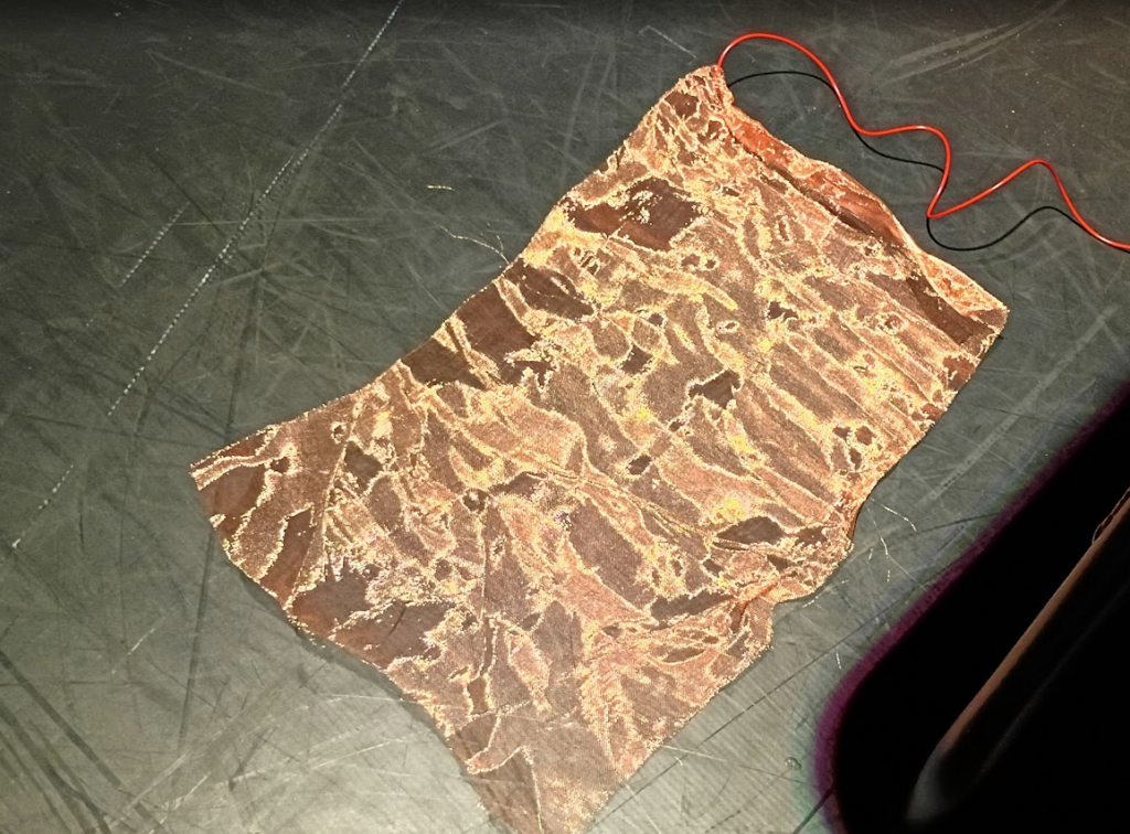
For this project I chose three technologies to explore, as shown above. First (left) is an ultrasonic sensor. It broadcasts an ultrasonic sound and listens for the returning echo. It is capable of detecting something within range as well as the distance the object is form the sensor. Second (center) is Infrared optical sensing. These are commonplace pieces of tech used to detect the presence of objects. A transmitter (clear LED) emits an IR beam of light. The receiver (black LED) detects the IR beam. If the path between the transmitter and detector is broken, the presence of an interfering object is detected. This is what usually prevents home garage doors form closing if something is in the way. Third (right) is a capacitive sensor. It detects the presence of an object by detecting a change in the state of charge across an electric circuit. See my PP3 for more information about how this works. For my tests I used a piece of copper mesh roughly 11×17 soldered to a length of wire (below). My cats were extremely interested in the mesh and kept triggering the sensor!
Cycle 3 includes two main parts. One, the electronics portion that explores the three sensor types mentioned above. The second piece is exploring how these inputs can be utilized by Isadora.
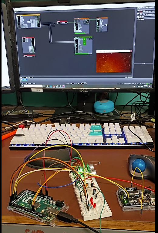
The photo above (my desk puts the MES in DEMS) shows the results of my efforts. On the left is an Arduino Mega controling the detection circuits and reporting to the PC and the user its status. The white piece in the middle is an electronics breadboard which contains the electrical components for the sensors. On the right is a smaller Arduino UNO loaded with the Firmata program that communicates with Isadora.
The system works by the Arduino Mega and the breadboard detecting the presence of a user then passing that information to the UNO, which then tells Isadora to do something. The Firmata User Actor, and its associated Arduino Firmware is an incredibly powerful and easy to use system that makes the task of getting GPIO in and out of Isadora. However, it does not provide easy means of expanding upon its functionality without essentially rewriting the Firmata software. This is why there is a second arduino, the mega, to handle the custom software needed to drive the detection circuits.
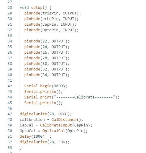
In an Arduino program, called a sketch, the first code that runs in part of a “setup” function. This is what tells the arduino what its ins and outs are as well as running any code that needs to happen before the main program takes over. Above is the code for my project. Lines 47-52 are the main interest here. The sensors require calibration before they can be used. The sensors need to know what the environment is like without the presence of a user so that it can compare that to when a user is nearby. Thus the first major step is to initialize each sensor type. Each sensor takes 10 readings, averages the results, and declares that is the default value. While this is happening an orange LED is illuminated on the breadboard to tell the operator that the system is in this process.
Once this step is completed, the system constantly takes readings from the sensors and compares the values to the calibration data, if the difference exceeds a threshold value a detection is registered. For convince the system also illuminates a red led to let the user know that a detection has occurred, there is a separate LED for each sensor. Here the user is the programmer, not the audience who is being detected. In addition to illuminating an LED to indicate that a sensor has detected something, a message is sent to the Isadora Arduino to let it know that there has been an event.
The Isadora scene is a straightforward affair. The Firmata actor is constantly monitoring the state of the Arduino Uno configured with the Firmata sketch via the Serial Bus. When pin2 goes high, a video is played. When pin3 goes high, an audio clip is played. Pin3 stops the audio. Pin4 resets a latch that keeps the video playing.
When the sensor electronics detects an acoustic trigger, it plays the video. When the optical sensor detects a change it plays the video, a second event stops the audio.
Expanding the Firmata Actor
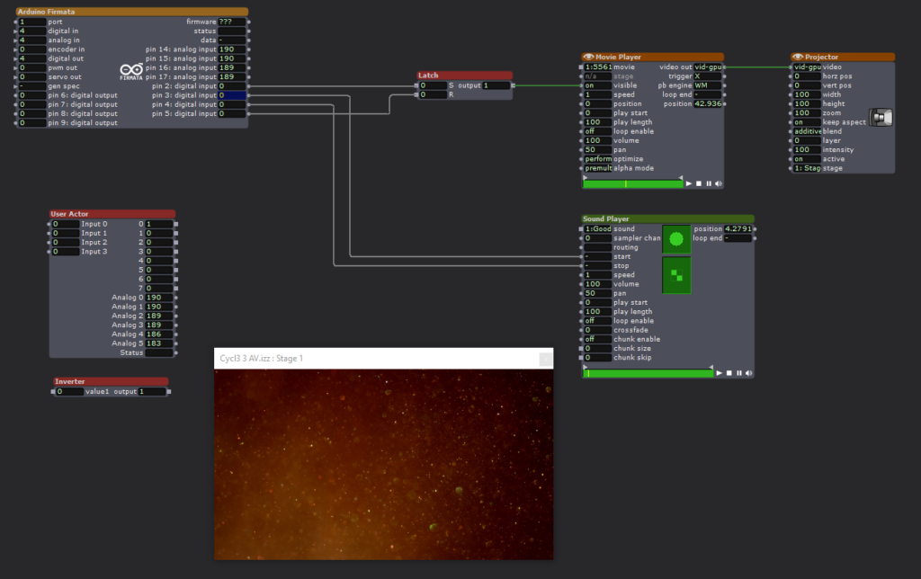
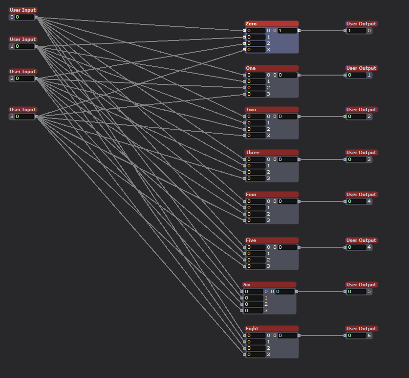
Above is a user actor that utilizes some additional logical processing to increase the number of inputs to Isadora. The Firmata Actor simply observes the digital pins of the connected Arduino to see if their input is either high or low. This is enough capability to implement binary decoding to allow the limited inputs to be expanded. As seen above, the user actor has 8 outputs, but the connected Arduino is only utilizing three of its physical inputs.
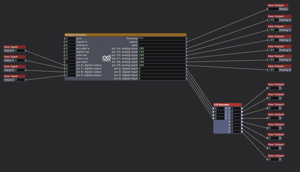
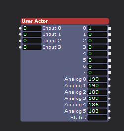
Looking inside the User Actor we can see the Firmata Actor with 4 digital inputs. We are ignoring the analog inputs for this exercise. Although there are four inputs shown, I am only using three of them to achieve 8 binary inputs. Utilizing all 4 physical inputs would allow for 16 binary inputs, but was not implemented here. The technical trick is occurring in the 3:8 Decoder user actor.
Inside the 3:8 Decoder actor we see that the four inputs are connected to 8 modules. These modules are the heart of the system.
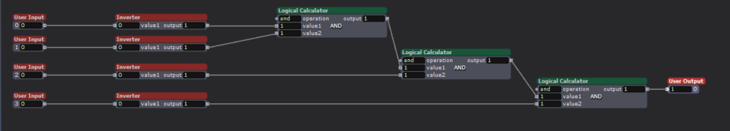
Using the Logical Calculator actor is is possible to implement Complementary Digital Logic. If you are interested please look into OSU ECE 2060 and ECE 5020.
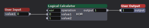
One final user actor was needed first, a digital inverter. This takes an input, either a 0 or 1, and outputs the opposite value. All that is needed is a Logical Calculator actor in XOR mode.
To implement Complementary Digital Logic, it is necessary to have the complement of a logical bit. In this case the opposite value of an input. For example, if Arduino input-1 is HIGH, we also need input-1! (input-1 Bar, or input-1 NOT). This tells the system that an input is NOT currently active. By combining the logical states of the three utilized physical inputs, with AND logical actors it becomes possible to encode additional states, to the value 2^(#inputs).
Currently the Arduino Mega processing the sensor input only has three sensors, but by encoding the status of the sensors it is possible to feed more sensor inputs into Isadora than would normally be possible using the Firmata actor. There are methods for passing serial data into Isadora to achieve even greater input count, but my method is technically simple to implement and is very robust and avoids complications that arise with serial communication protocols.
Putting all of this together for my home DEMS
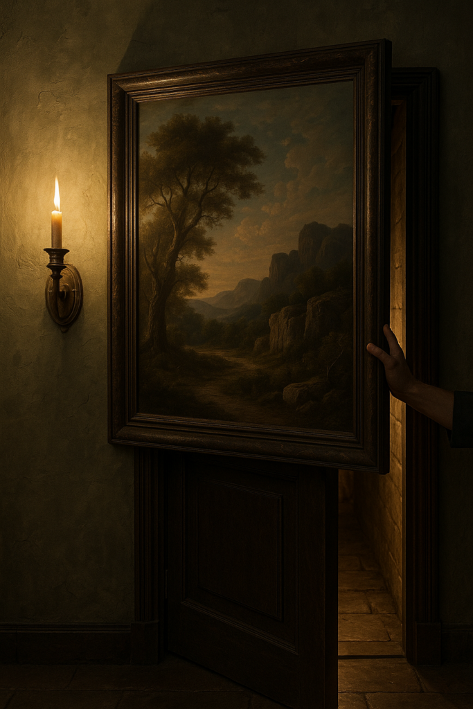
A key part of my home DEMS is the creation of several secret doors. These are implemented by having sections of a wall sliding away to reveal the passageway. Just like an elevator, it is vital that the doors do not close on anyone (See my PP1, no chomping here). The IR optical sensor will work well for this use case. It is simple and works in a vary direct line of sigh manner. If anything breaks the beam it means that there is an obstruction in the doorway. By monitoring this sensor the door control can know not to close on anyone, or the cats.

What sort of mysterious home would I have without a giant, vaguely threatening, carnivorous plant! Certainly not one worth visiting. It is a goal to have such a character at home. Some type of large carniverous plant, think Audrey but cuter. I want the plant to follow people as they walk past, and if they get close enough I want it to take a chomp at them. This is the perfect place to utilize the ultrasonic sensor. By placing several such sensors around the plant it will be possible to detect the presence of a person as well as knowing how far away they are. With this data the plant can track them and eventually try and take a bite!
The optical and ultrasonic sensors are discrete and the light and sound they produce is undetectable by humans, but they require line of sight to work. Neither can work if they are completely enclosed or obscured. The IR detector is tiny, but does require a hole of some kind for the light to pass through (or an IR transparent window). The capacitive sensor is different, it can be completely hidden. The metal mesh that acts as the sensor can be hidden under carpet, behind a painting, under a tablecloth, even in the fabric of a pillow or cushion. I envision using it to detect when someone enters a room or if they are reaching to grab an object. For example, imagine a crystal ball sitting in the center of a table. By hiding the sensor under a small tablecloth it is possible to detect when someone reaches out to the ball, without actually touching anything. This could trigger some other effect such as the ball glowing or a sound playing.
If nothing else, the sensor made a good cat toy. Biscuit approves (below)! I had to cover it with an empty cereal box to keep them form clawing at it, but then they became very curious about the box! There was no winning.